Review
. 2014 Jan 16:5:3.
doi: 10.3389/fmicb.2014.00003. eCollection 2014.

Structures and host-adhesion mechanisms of lactococcal siphophages

Affiliations
Review

Structures and host-adhesion mechanisms of lactococcal siphophages

Silvia Spinelli et al. Front Microbiol. .

Abstract

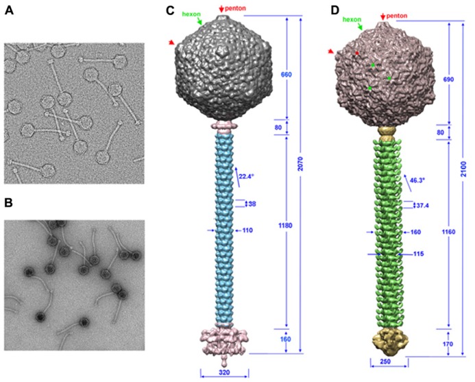
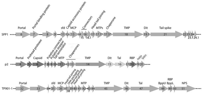
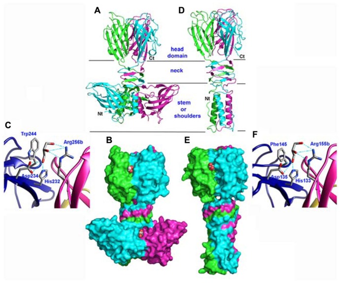
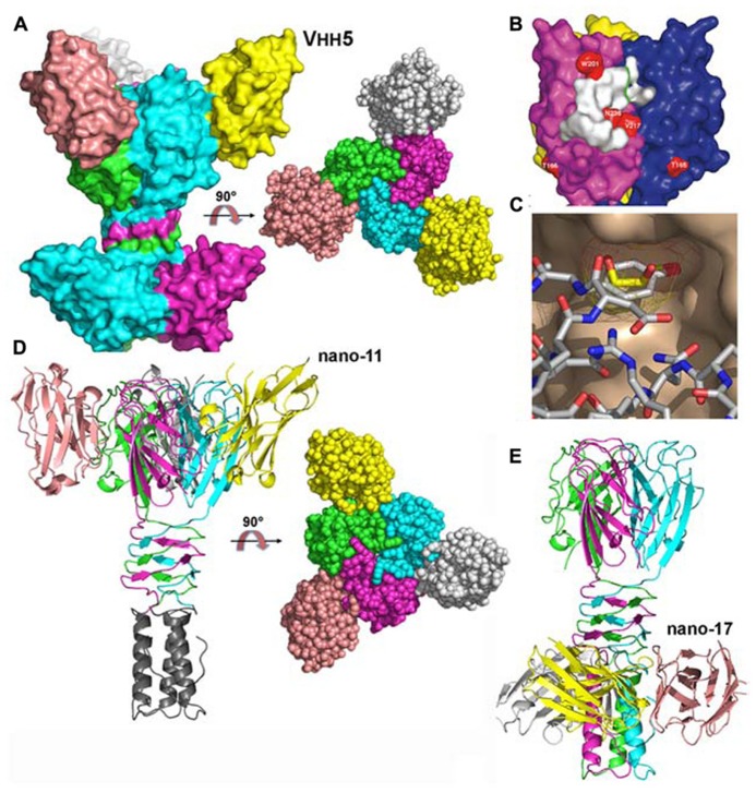
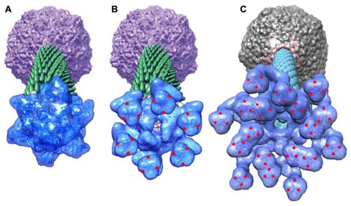
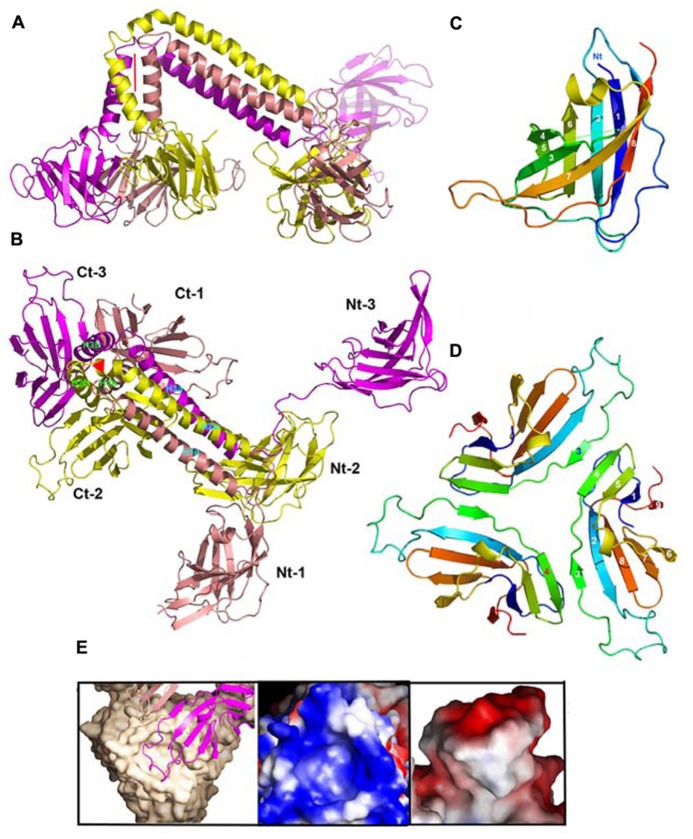
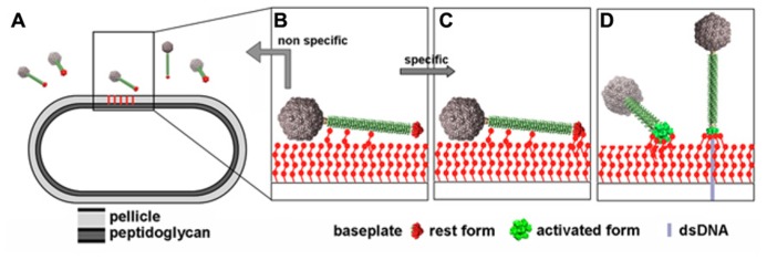
The Siphoviridae family of bacteriophages is the largest viral family on earth and comprises members infecting both bacteria and archaea. Lactococcal siphophages infect the Gram-positive bacterium Lactococcus lactis, which is widely used for industrial milk fermentation processes (e.g., cheese production). As a result, lactococcal phages have become one of the most thoroughly characterized class of phages from a genomic standpoint. They exhibit amazing and intriguing characteristics. First, each phage has a strict specificity toward a unique or a handful of L. lactis host strains. Second, most lactococcal phages possess a large organelle at their tail tip (termed the baseplate), bearing the receptor binding proteins (RBPs) and mediating host adsorption. The recent accumulation of structural and functional data revealed the modular structure of their building blocks, their different mechanisms of activation and the fine specificity of their RBPs. These results also illustrate similarities and differences between lactococcal Siphoviridae and Gram-negative infecting Myoviridae.

Keywords: Lactococcus lactis; Siphoviridae; bacteriophage; crystal structure; electron microscopy.


Figures

FIGURE 1
FIGURE 1
The TP901-1 and p2 phages assembled structures. (A,B) Electron microscopy images of phages TP901-1 (A) and p2 (B). (C,D) The structures of phage TP901-1 (C) and p2 (D) were generated by assembling the reconstructions of the capsid (top), connector and tail (middle), and the tail-tip (bottom) on low-resolution maps of the full phages. In the capsid map, pentons are identified by red arrows/points and hexons by green arrows/points. Dimensions are given in Å and the angle of rotation between MTP hexamers is given in degrees.
FIGURE 2
FIGURE 2
Schematic representation and assignment of the structural gene module of phages SPP1, p2, and TP901-1. Genes coding for non-structural ORFs are in light gray. Sfd, scaffolding; MCP, major capsid protein; MTP, major tail protein; TMP, tail tape measure protein; Dit, distal tail protein; Tal, tail-associated lysine; RBP, receptor binding protein; BppU, baseplate upper protein; BppL, baseplate lower protein; NPS, neck passage structure. * indicates alternate splicing.
FIGURE 3
FIGURE 3
Structures of the receptor binding proteins (RBPs) of phages p2 and TP901-1. (A,D) Ribbon view of the p2 RBP trimer (A) and of the TP901-1 RBP trimer (D). Monomers are colored green, blue, and pink. (B,E) Surface representation of the p2 RBP trimer (B) and of the TP901-1 RBP trimer (E). Bound glycerol molecules are represented by spheres (carbon, white; oxygen, red). (C,F) Close-up view of glycerol in the receptor binding site of the RBPs of phages p2 (C) and TP901-1 (F). The glycerol molecule and the side-chains of the residues participating to binding are represented as sticks (carbon, white; oxygen, red; nitrogen, blue).
FIGURE 4
FIGURE 4
Structures of the receptor binding proteins (RBPs) of phages p2 and TP901-1 in complex with VHHs/nanobodies. (A) Surface representation of the p2 RBP trimer in complex with the neutralizing VHH5 (nano5), and 90° rotated view. (B) Surface footprint of VHH5 on the RBP trimer surface (white). Mutated residues leading to neutralization escape are indicated in red. (C) View of the superposition of the VHH5 Tyr 55 with glycerol. The RBP surface is colored beige, the glycerol carbon atoms are yellow, while those of VHH5 are white. Oxygen atoms are red and nitrogen atoms are blue. (D) Ribbon view of the TP901-1 RBP trimer in complex with the neutralizing nanobody 11 and surface view at 90° (right). (E) Ribbon view of the TP901-1 RBP trimer in complex with the non-neutralizing nanobody 17. Panels (B,C) taken from Tremblay et al. (2006). Copyright © American Society for Microbiology.
FIGURE 5
FIGURE 5
The “pellicle” phospho-polysaccharide from L. lactis MG1363 (. This phospho-polysaccharide is the receptor of lactococcal phages sk1 and p2.
FIGURE 6
FIGURE 6
The crystal structures of the baseplates of phages p2 and TP901-1. (A) Side-view of the phage p2 baseplate rest form in complex with the llama VHH5 (ORF15/Dit, green; ORF16/Tal, red; ORF18/RBP, blue; VHH5, gray). (B) Top-view of the phage p2 baseplate rest form (same colors are in A, but the VHH5 has been removed from the view). (C) Side-view of the phage p2 baseplate Sr2+/Ca2+ activated form (same colors as in A). (D) Top-view of the phage p2 baseplate Sr2+/Ca2+ activated form. (E) Side-view of the phage TP901-1 baseplate (ORF46/Dit, green; ORF48/BppU, orange; ORF49/RBP, violet). (F) Side-view of the phage TP901-1 baseplate (same colors as in E).
FIGURE 7
FIGURE 7
Crystal structures of components of phages baseplates. (A) Superimposition of the Dit hexamers structures from phages TP901-1 (ORF46, green), p2 (ORF15, purple), and SPP1 (gp19.1, gold). (B) Ribbon view of the crystal structure of ORF16/Tal from the p2 baseplate in the rest form (rainbow coloring, from blue to red). (C) Surface view of the closed ORF16/Tal trimer from the p2 baseplate in the rest form. (D) Crystal structure of ORF16/Tal from the p2 baseplate in the Sr2+/Ca2+ activated form. Domain 4 has moved away from the rest of the molecule. (E) Surface view of the open ORF16/Tal trimer from the p2 baseplate in the Sr2+/Ca2+ activated form.
FIGURE 8
FIGURE 8
A composite X-ray/EM reconstruction of the p2 baseplate. (A) A 20 Å electron density map (blue; ribbon structure inside) of the rest form (free virion) of the p2 baseplate crystal structure was calculated and subtracted from the baseplate experimental EM map. The resulting difference map (yellow) corresponds to a Dit (ORF15) hexamer. (B) A 20 Å electron density map (blue; ribbon structure inside) of the activated form of the p2 baseplate crystal structure was calculated and appended to the upper Dit EM map (yellow). Figure adapted from Bebeacua et al. (2013b). Copyright © American Society for Microbiology.
FIGURE 9
FIGURE 9
Perspective views of the reconstructions of the p2 phage. (A) The baseplate rest form and (B) the Ca++ activated form, showing in forefront the baseplate structure, closed and opened, respectively. (C) The TP901-1 baseplate. The red dots are located at the RBP saccharides binding sites in the activated phage p2 and in the phage TP901-1 representations. Red arrow identifies the open channel of phage p2 activated baseplate. Panels (A,B) adapted from Bebeacua et al. (2013b). Copyright © American Society for Microbiology.
FIGURE 10
FIGURE 10
Structures of components of phage TP901-1 baseplate. (A) Lateral ribbon view of the ORF48 trimer (salmon, yellow, and violet, for monomers 1, 2, and 3, respectively). (B) View 90° from (A) (top view) of ORF48 trimer. The N- and C-terminal domains are labeled, 1, 2, 3, respectively. (C) The ribbon view (rainbow colored) of the N-terminal domain of ORF48. (D) The ribbon view (rainbow colored) of a trimer of the C-terminal domain of ORF48. (E) Left to right: Close-up view of the electrostatic surface potential of the interacting regions from BppU and the RBP highlighting their high charge and surface complementarity. Each RBP trimer (beige) is anchored to the baseplate via a loop extending from each BppU C-terminal domain (pink) that penetrates the cup formed at the top of this former protein.
FIGURE 11
FIGURE 11
Putative infection mechanism of L. lactis MG1363 by phage p2. (A) The phages in the vicinity of the host. (B) Weak interactions are established between the tail adhesins and putatively the pellicle. (C) Strain-specific lateral interactions may occur between the phage RBPs of the resting baseplate and the specific pellicle, leading, in the presence of Ca++ to (D) baseplate activation, RBPs rotation, and strong binding involving several of the 18 saccharide binding sites. Figure taken from Bebeacua et al. (2013b). Copyright © American Society for Microbiology.

References

    1. Abdallah A. M., Gey Van Pittius N. C., Champion P. A., Cox J., Luirink J., Vandenbroucke-Grauls C. M., et al. (2007). Type VII secretion – mycobacteria show the way. Nat. Rev. Microbiol. 5 883–89110.1038/nrmicro1773 - DOI - PubMed
    1. Andre G., Kulakauskas S., Chapot-Chartier M. P., Navet B., Deghorain M., Bernard E., et al. (2010). Imaging the nanoscale organization of peptidoglycan in living Lactococcus lactis cells. Nat. Commun. 1 1–810.1038/ncomms1027 - DOI - PMC - PubMed
    1. Auzat I., Droge A., Weise F., Lurz R., Tavares P. (2008). Origin and function of the two major tail proteins of bacteriophage SPP1. Mol. Microbiol. 70 557–56910.1111/j.1365-2958.2008.06435.x - DOI - PubMed
    1. Babu K. S., Spence W. S., Monteville M. R., Geller B. L. (1995). Characterization of a cloned gene (pip) from Lactococcus lactis required for phage infection. Dev. Biol. Stand. 85 569–575 - PubMed
    1. Bebeacua C., Bron P., Lai L., Vegge C. S., Brondsted L., Spinelli S., et al. (2010). Structure and molecular assignment of lactococcal phage TP901-1 baseplate. J. Biol. Chem. 285 39079–3908610.1074/jbc.M110.175646 - DOI - PMC - PubMed