. 2014 Mar;11(3):313-8.
doi: 10.1038/nmeth.2835. Epub 2014 Feb 2.

Multiplexed 3D cellular super-resolution imaging with DNA-PAINT and Exchange-PAINT

Affiliations

Multiplexed 3D cellular super-resolution imaging with DNA-PAINT and Exchange-PAINT

Ralf Jungmann et al. Nat Methods. 2014 Mar.

Abstract

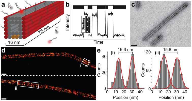
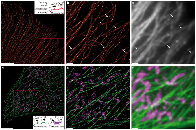
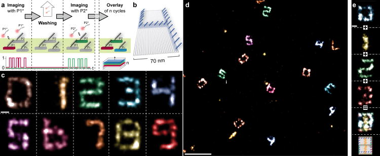
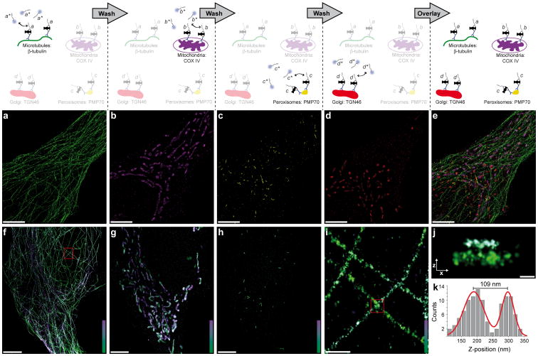
Super-resolution fluorescence microscopy is a powerful tool for biological research, but obtaining multiplexed images for a large number of distinct target species remains challenging. Here we use the transient binding of short fluorescently labeled oligonucleotides (DNA-PAINT, a variation of point accumulation for imaging in nanoscale topography) for simple and easy-to-implement multiplexed super-resolution imaging that achieves sub-10-nm spatial resolution in vitro on synthetic DNA structures. We also report a multiplexing approach (Exchange-PAINT) that allows sequential imaging of multiple targets using only a single dye and a single laser source. We experimentally demonstrate ten-color super-resolution imaging in vitro on synthetic DNA structures as well as four-color two-dimensional (2D) imaging and three-color 3D imaging of proteins in fixed cells.


Figures

Figure 1
Figure 1
DNA-PAINT. (a) A microtubule-like DNA origami polymer (cylinders represent DNA double helices) is decorated with single-stranded extensions (docking strands) on two opposite faces (colored in red) spaced ≈16 nm apart. Complementary fluorescent imager strands transiently bind from solution to docking strands. Biotinylated strands (present on orange colored helices) immobilize the structures to glass surfaces for fluorescence imaging. (b) Transient binding between imager and docking strands produces fluorescence blinking, allowing stochastic super-resolution imaging. (c) TEM image of origami polymers with a measured width of 16 ± 1 nm (mean ± stdv). Scale bar: 40 nm. (d) DNA-PAINT super-resolution images obtained using Cy3b-labeled imager strands (15,000 frames, 5 Hz frame rate). Two distinct lines are visible. Scale bars: 40 nm. (e) Cross-sectional histograms of highlighted areas <i> and <ii> in d (arrows denoting histogram direction) both reveal designed distance of ≈16 nm (FWHM of each distribution is ≈7–10 nm).
Figure 2
Figure 2
Spectrally multiplexed DNA-PAINT super-resolution imaging of microtubules and mitochondria inside fixed cells. (a) DNA-PAINT super-resolution image of microtubules inside a fixed HeLa cell using Atto655-labeled imager strands (10,000 frames, 10 Hz frame rate). Scale bar: 5 μm. Inset: Labeling and imaging schematic for DNA-PAINT in a cellular environment. Microtubules are labeled with a pre-assembled antibody-DNA conjugate, which is formed between a biotinylated anti-tubulin antibody and a biotinylated DNA docking strand using a streptavidin bridge. (b) Zoom-in of the highlighted area in a. Scale bar: 1 μm. (c) Diffraction-limited representation of the same area as in b. Arrows highlight positions where the increase in resolution of the DNA-PAINT image is clearly visible. Adjacent microtubules with an apparent width of ≈46 nm at position <i> are separated by ≈79 nm (see Supplementary Figure 5 for enlarged image and quantification details). Scale bar: 1 μm. (d) Dual-color DNA-PAINT super-resolution image (15,000 frames, 10 Hz frame rate) of microtubules and mitochondria inside a fixed HeLa cell obtained using Cy3b-labeled imager strands for microtubules (green) and orthogonal ATTO655-labeled imager strands for mitochondria (magenta). Scale bar: 5 μm. Inset: Labeling and imaging schematic. (e) Zoom-in of the highlighted area in d. Scale bar: 1 μm. (f) Diffraction-limited image of the same area as in e. Scale bar: 1 μm.
Figure 3
Figure 3
Exchange-PAINT. (a) Exchange-PAINT schematic. Targets are labeled with orthogonal docking strands (P1, P2, etc.). In the first imaging round, only imager strands P1* are present and targets P1 are specifically imaged (Binarized intensity vs. time traces at the bottom show specific blinking of only P1 targets) and assigned a red pseudocolor. After acquisition, P1* strands are washed out and exchanged with imager strands P2*, and targets P2 are specifically imaged and assigned a green pseudocolor. All imager strands are labeled with the same fluorophore. Imaging and washing is repeated until all targets are imaged. A distinct pseudocolor is assigned in each imaging round. (b) Schematic of a DNA origami (70 × 100 nm) displaying docking strands that resemble digit 4. (c) Pseudocolor images of ten different origamis displaying digits 0 to 9 in one sample with high resolution (FWHM of bar-like features < 10 nm) and specificity. Image obtained using only one fluorophore (Cy3b) through ten imaging-washing cycles (imaging: 7,500 frames per cycle, 5 Hz frame rate; washing: 1-2 minutes per cycle). Scale bar: 25 nm. (d) Combined overview image of all ten Exchange-PAINT cycles, demonstrating specific interaction with the respective target with no crosstalk between imaging cycles. Scale bar: 250 nm. (e) Four-“color” image of digits 0 to 3 that are all present on the same DNA origami (10,000 frames each, 5 Hz frame rate; schematic at the bottom). Scale bar: 25 nm.
Figure 4
Figure 4
Multiplexed 2D and 3D Exchange-PAINT super-resolution imaging in fixed cells. (Top) Schematic of experimental procedure. (Center) 2D Exchange-PAINT images. (Bottom) 3D Exchange-PAINT images. Each target is labeled with an antibody carrying a unique DNA-PAINT docking sequence. 2D and 3D imaging is performed using imager strands labeled with ATTO655 and Cy3b, respectively. (a–e) Four-“color” 2D images using ATTO655-labeled imager strands. (a) Only imager strands a* are present, and microtubules are specifically imaged. (b) After washing out imager strands a*, imager strands b* are introduced and COX IV proteins in mitochondria are imaged. TGN46 proteins in the Golgi complex (c) and PMP70 proteins in peroxisomes (d) are imaged in the same way (Imaging: 15,000 frames per cycle, 10 Hz imaging rate; washing: 1-2 minutes per cycle). (e) Overlay of all four targets. (f–k) 3-“color” 3D images using Cy3b-labeled imager strands. (f) 3D image of microtubules, color indicates height. Height scale: 0 nm – 800 nm. (g) 3D image of mitochondria. Height scale: 40 nm – 1100 nm. (h) 3D image of peroxisomes. Height scale: 0 nm – 700 nm. (i) Zoom-in of the highlighted area in f. Height scale: 0 nm – 700 nm. (j) X-Z-profile of the highlighted area in i. (k) A two-component Gaussian fit reveals a distance of ≈109 nm in z of two adjacent microtubules. For 3D imaging: 50,000 frames per cycle, 16 Hz imaging rate; washing: 1-2 minutes per cycle. Scale bars in a–h: 5 μm; scale bar in i: 500 nm; scale bar in j: 100 nm.

Similar articles

Cited by

References

    1. Rust MJ, Bates M, Zhuang X. Sub-diffraction-limit imaging by stochastic optical reconstruction microscopy (STORM) Nat Methods. 2006;3:793–5. - PMC - PubMed
    1. Hell SW. Microscopy and its focal switch. Nature methods. 2009;6:24–32. - PubMed
    1. Hell SW, Wichmann J. Breaking the diffraction resolution limit by stimulated emission: stimulated-emission-depletion fluorescence microscopy. Opt Lett. 1994;19:780–2. - PubMed
    1. Betzig E, et al. Imaging intracellular fluorescent proteins at nanometer resolution. Science. 2006;313:1642–5. - PubMed
    1. Sharonov A, Hochstrasser RM. Wide-field subdiffraction imaging by accumulated binding of diffusing probes. Proceedings of the National Academy of Sciences of the United States of America. 2006;103:18911–18916. - PMC - PubMed

Publication types