. 2013:2013:270579.
doi: 10.1155/2013/270579. Epub 2013 Dec 29.

Imaging of cardiac valves by computed tomography

Affiliations

Imaging of cardiac valves by computed tomography

Gudrun Feuchtner. Scientifica (Cairo). 2013.

Abstract

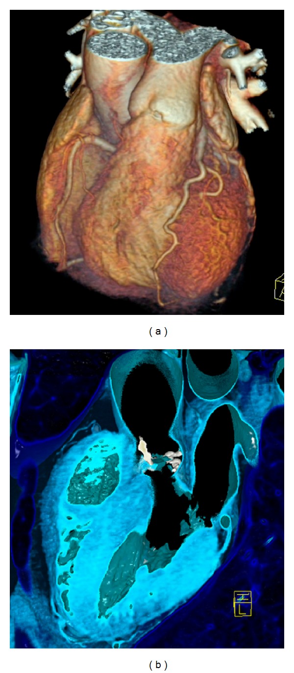
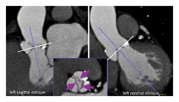
This paper describes "how to" examine cardiac valves with computed tomography, the normal, diseased valves, and prosthetic valves. A review of current scientific literature is provided. Firstly, technical basics, "how to" perform and optimize a multislice CT scan and "how to" interpret valves on CT images are outlined. Then, diagnostic imaging of the entire spectrum of specific valvular disease by CT, including prosthetic heart valves, is highlighted. The last part gives a guide "how to" use CT for planning of transcatheter aortic valve implantation (TAVI), an emerging effective treatment option for patients with severe aortic stenosis. A special focus is placed on clinical applications of cardiac CT in the context of valvular disease.


Figures

Figure 1
Figure 1
(a) 3-D VRT image of the heart by computed tomography. The coronary arteries (LAD—left anterior descending—in the front) are shown. Cardiac valve evaluation from same CT data set is possible. (see pulmonary valve in the front). (b) 3-D image of the aortic valve. Severe calcification (white color) of the aortic valve are pathognomonic for degenerative aortic stenosis (here shown in 3-chamber view). Further, quantification and characterization of aortic valve and annulus calcium predict complications during transcatheter aortic valve implantation (TAVI) such as postsurgery paravalvular regurgitation or annulus rupture during stent expansion.
Figure 2
Figure 2
Aortic stenosis: Aortic valve area (AVA) sizing by CT. Using 3-multiplanar reformations (MPR), from left sagittal oblique (left) and left coronal oblique (right) views, a cross-sectional view of the aortic valve is generated (lower mid image). The white line indicates the plane of the cross-sectional axial oblique view in the low midimage inlay, which allows quantification of the inner aortic valve orifice area (AVA) (pink arrows). This area is traced by a digital caliper and reflects a marker for the severity of aortic stenosis (<1 cm2: severe critical). Valve morphology was bicuspid (fused raphe).
Figure 3
Figure 3
Papillary fibroelastoma of the aortic valve: a round-shaped hypodense mass. The mass is attached to the noncoronary cusp (black arrow). Cross-sectional view of the aortic root.
Figure 4
Figure 4
Mitral annulus ring calcification (MAC) hyperintense (big white arrow). This patient also had infective endocarditis; therefore, a mitral valve vegetation—hypodense-black (round, mass like) left-sided (black arrow) was found, attached to the calcified mitral ring. Short axis view of the mitral valve.
Figure 5
Figure 5
Metallic mechanic prosthetic valve by CT: 3-D VRT reconstructions permit the evaluation of leaflet dysfunction and valve obstruction. Here: St. Jude mechanic aortic valve, closed during diastole (normal finding). These valves cause artifacts of echo; hence, CT can act as troubleshooter in case of suspected dysfunction or infection.
Figure 6
Figure 6
Aortoiliac CT Angiography for planning of transcatheter aortic valve implantation (TAVI), using high-pitch 128-dual source CT. Severe calcifications of the abdominal aorta but the right iliac artery are spared from atherosclerosis and do not show tortousity. Transfemoral access was possible via the right iliac artery.
Figure 7
Figure 7
Aortic annulus sizing by CT. (a): The anterior-posterior (AP) (D3) and mediolateral diameter (ML) (D4) are measured on cross-sectional images. The mean of both diameters is commonly calculated for selecting the appropriate size of the transcatheter aortic valve prosthesis device finally used for TAVI (currently, 23 mm, 26 mm, or 29 mm devices). Exact fit is crucial to avoid paravalvular leakage and to ensure seamless adaption of the prosthesis with the aortic annulus. (b): Quantification of the annulus area is another valuable parameter for selection of the final valve size. Aortic annulus area is traced with a digital caliper (Area, 475 mm2).

References

    1. Feuchtner G, Goetti R, Plass A, et al. Dual-step prospective ECG-triggered 128-slice dual-source ct for evaluation of coronary arteries and cardiac function without heart rate control: a technical note. European Radiology. 2010;20(9):2092–2099. - PubMed
    1. Achenbach S, Marwan M, Ropers D, et al. Coronary computed tomography angiography with a consistent dose below 1 mSv using prospectively electrocardiogram-triggered high-pitch spiral acquisition. European Heart Journal. 2010;31(3):340–346. - PubMed
    1. Leschka S, Stolzmann P, Desbiolles L, et al. Diagnostic accuracy of high-pitch dual-source CT for the assessment of coronary stenoses: first experience. European Radiology. 2009;19(12):2896–2903. - PubMed
    1. Alkadhi H, Stolzmann P, Desbiolles L, et al. Low-dose, 128-slice, dual-source CT coronary angiography: accuracy and radiation dose of the high-pitch and the step-and-shoot mode. Heart. 2010;96(12):933–938. - PubMed
    1. Marwan M, Pflederer T, Schepis T, et al. Accuracy of dual-source computed tomography to identify significant coronary artery disease in patients with atrial fibrillation: comparison with coronary angiography. European Heart Journal. 2010;31(18):2230–2237. - PubMed