

Biomechanics of the natural, arthritic, and replaced human ankle joint
- PMID: 24499639
- PMCID: PMC3918177
- DOI: 10.1186/1757-1146-7-8
Biomechanics of the natural, arthritic, and replaced human ankle joint
Abstract
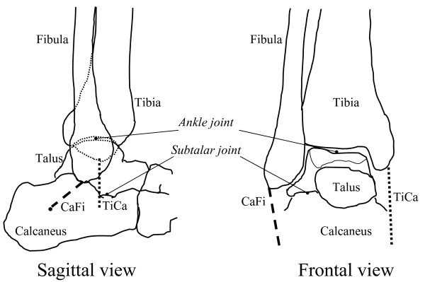
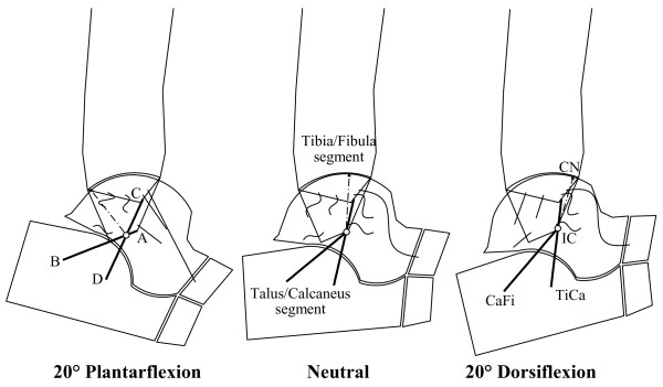
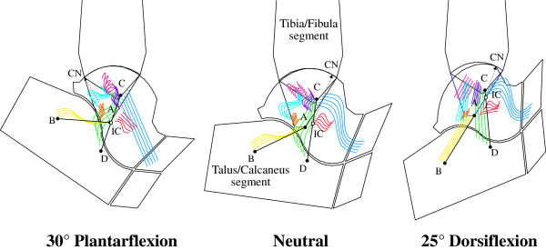
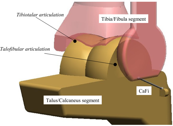
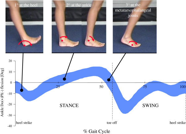
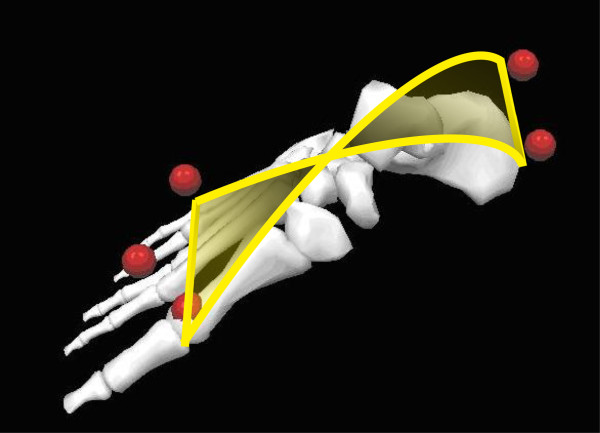
The human ankle joint complex plays a fundamental role in gait and other activities of daily living. At the same time, it is a very complicated anatomical system but the large literature of experimental and modelling studies has not fully described the coupled joint motion, position and orientation of the joint axis of rotation, stress and strain in the ligaments and their role in guiding and stabilizing joint motion, conformity and congruence of the articular surfaces, patterns of contact at the articular surfaces, patterns of rolling and sliding at the joint surfaces, and muscle lever arm lengths.The present review article addresses these issues as described in the literature, reporting the most recent relevant findings.
Figures
Similar articles
-
The role of the passive structures in the mobility and stability of the human ankle joint: a literature review.Foot Ankle Int. 2000 Jul;21(7):602-15. doi: 10.1177/107110070002100715. Foot Ankle Int. 2000. PMID: 10919630 Review.
-
Prediction of three-dimensional contact stress and ligament tension in the ankle during stance determined from computational modeling.Foot Ankle Int. 2009 Feb;30(2):177-85. doi: 10.3113/FAI-2009-0177. Foot Ankle Int. 2009. PMID: 19254515
-
Dynamic simulation of the natural and replaced human ankle joint.Med Biol Eng Comput. 2002 Mar;40(2):193-9. doi: 10.1007/BF02348124. Med Biol Eng Comput. 2002. PMID: 12043800
-
A geometric model of the human ankle joint.J Biomech. 1999 Jun;32(6):585-91. doi: 10.1016/s0021-9290(99)00022-6. J Biomech. 1999. PMID: 10332622
-
Biomechanics of the distal radioulnar joint.Clin Orthop Relat Res. 1992 Feb;(275):46-55. Clin Orthop Relat Res. 1992. PMID: 1735232 Review.
Cited by
-
A new ligament-compatible patient-specific 3D-printed implant and instrumentation for total ankle arthroplasty: from biomechanical studies to clinical cases.J Orthop Traumatol. 2020 Sep 2;21(1):16. doi: 10.1186/s10195-020-00555-7. J Orthop Traumatol. 2020. PMID: 32876778 Free PMC article.
-
Incorporating pathological gait into patient-specific finite element models of the haemophilic ankle.Biomech Model Mechanobiol. 2024 Oct;23(5):1607-1616. doi: 10.1007/s10237-024-01857-z. Epub 2024 May 20. Biomech Model Mechanobiol. 2024. PMID: 38763978 Free PMC article.
-
Navigating the Divide: A Comprehensive Review of the Mechanical and Anatomical Axis Approaches in Total Knee Replacement.Cureus. 2024 Apr 9;16(4):e57938. doi: 10.7759/cureus.57938. eCollection 2024 Apr. Cureus. 2024. PMID: 38738158 Free PMC article. Review.
-
Centre of Rotation of the Human Subtalar Joint Using Weight-Bearing Clinical Computed Tomography.Sci Rep. 2020 Jan 23;10(1):1035. doi: 10.1038/s41598-020-57912-z. Sci Rep. 2020. PMID: 31974489 Free PMC article.
-
Indications, Functional Outcomes, Return to Sport and Complications of Anterior and Lateral Approaches for Total Ankle Arthroplasty: A Comprehensive Review.Healthcare (Basel). 2025 Apr 7;13(7):841. doi: 10.3390/healthcare13070841. Healthcare (Basel). 2025. PMID: 40218138 Free PMC article. Review.
References
-
- Hamblen DL. Can the ankle joint be replaced? J Bone Joint Surg Br. 1985;67(5):689–690. - PubMed
-
- O’Connor JJ, Lu TW, Wilson DR, Feikes J, Leardini A. Review: diarthrodial joints-kinematic pairs, mechanisms or flexible structures? Comput Methods Biomech Biomed Engin. 1998;1(2):123–150. - PubMed
-
- Goodfellow J, O’Connor JJ. The mechanics of the knee and prosthesis design. J Bone Joint Surg Br. 1978;60-B(3):358–369. - PubMed
-
- Katcherian DA. Treatment of ankle arthrosis. Clin Orthop Relat Res. 1998;349:48–57. - PubMed
LinkOut - more resources
Full Text Sources
Other Literature Sources
