

A planar PDMS micropump using in-contact minimized-leakage check valves
- PMID: 24511208
- PMCID: PMC3915938
- DOI: 10.1088/0960-1317/20/9/095033
A planar PDMS micropump using in-contact minimized-leakage check valves
Abstract
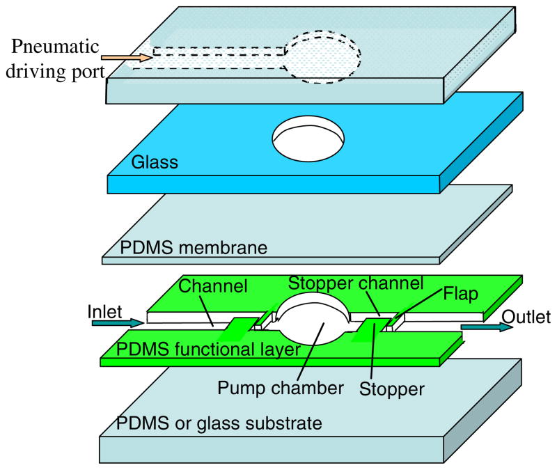
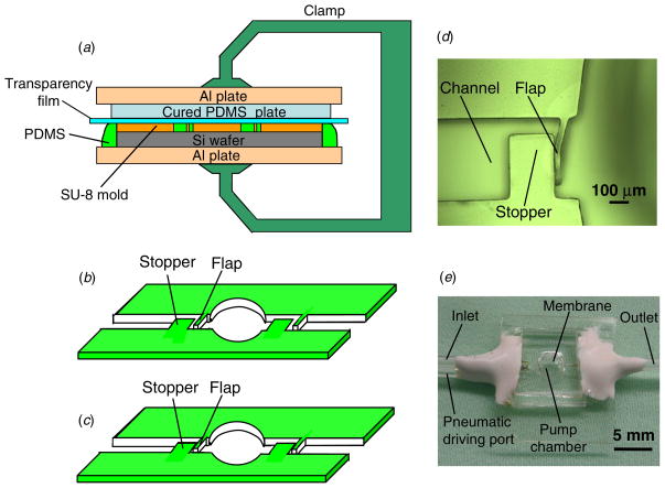
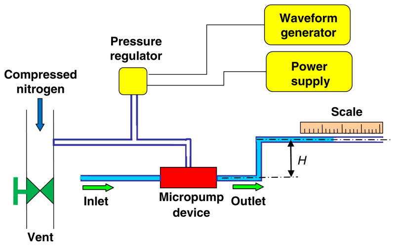
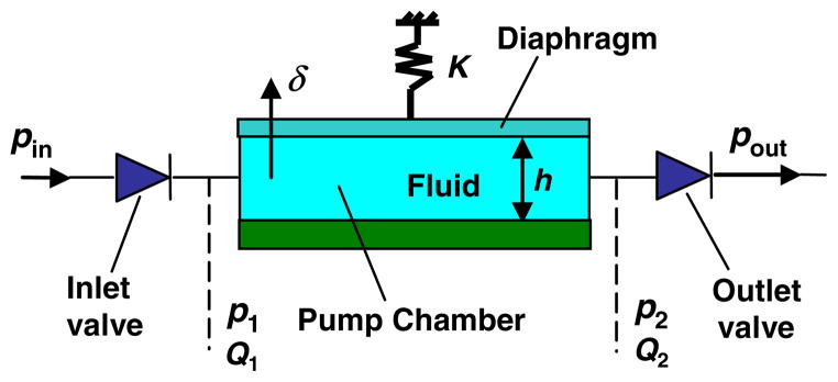
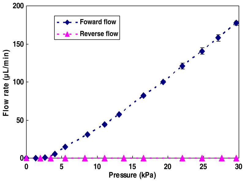
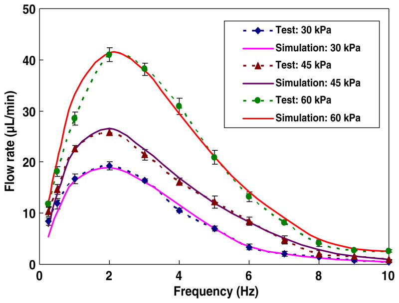
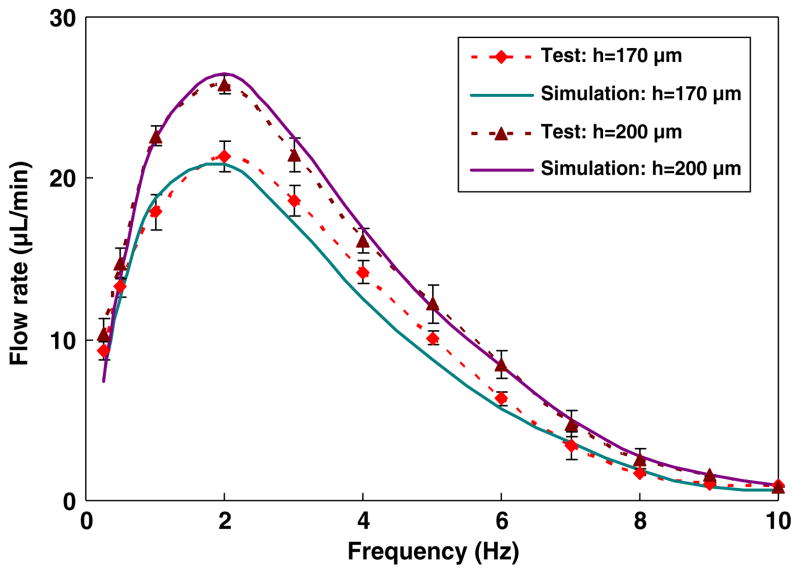
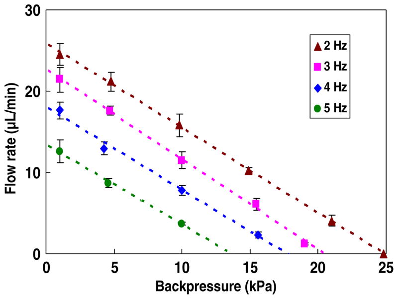
We present a micropump with a simple planar design featuring compliant in-contact check valves in a single layer, which allows for a simple structure and easy system integration. The micropump, based on poly(dimethylsiloxane) (PDMS), primarily consists of a pneumatically driven thin membrane, a pump chamber, and two in-plane check valves. The pair of check valves is based on an in-contact flap-stopper configuration and is able to minimize leakage flow, greatly enhancing the reliability and performance of the micropump. Systematic experimental characterization of the micropump has been performed in terms of the frequency response of the pumping flow rate with respect to factors including device geometry (e.g. chamber height) and operating parameters (e.g. pneumatic driving pressure and backpressure). The results demonstrate that this micropump is capable of reliably generating a maximum flow rate of 41 μL min-1 and operating against a high backpressure of up to 25 kPa. In addition, a lumped-parameter theoretical model for the planar micropump is also developed for accurate analysis of the device behavior. These results demonstrate the capability of this micropump for diverse applications in lab-on-a-chip systems.
Figures
Similar articles
-
An integrated planar magnetic micropump.Microelectron Eng. 2014 Apr 1;117:35-40. doi: 10.1016/j.mee.2013.11.014. Epub 2013 Dec 19. Microelectron Eng. 2014. PMID: 33551527 Free PMC article.
-
SU8 diaphragm micropump with monolithically integrated cantilever check valves.Lab Chip. 2011 Oct 7;11(19):3320-5. doi: 10.1039/c1lc20324j. Epub 2011 Aug 19. Lab Chip. 2011. PMID: 21853192
-
Assembly and simple demonstration of a micropump installing PDMS-based thin membranes as flexible micro check valves.J Biomed Nanotechnol. 2009 Oct;5(5):516-20. doi: 10.1166/jbn.2009.1057. J Biomed Nanotechnol. 2009. PMID: 20201426
-
Optimization of Micropump Performance Utilizing a Single Membrane with an Active Check Valve.Micromachines (Basel). 2017 Dec 21;9(1):1. doi: 10.3390/mi9010001. Micromachines (Basel). 2017. PMID: 30393278 Free PMC article.
-
Piezoelectric micropump with integrated elastomeric check valves: design, performance characterization and primary application for 3D cell culture.Biomed Microdevices. 2023 Jan 17;25(1):5. doi: 10.1007/s10544-022-00645-9. Biomed Microdevices. 2023. PMID: 36648587
Cited by
-
A Review of Capillary Pressure Control Valves in Microfluidics.Biosensors (Basel). 2021 Oct 19;11(10):405. doi: 10.3390/bios11100405. Biosensors (Basel). 2021. PMID: 34677361 Free PMC article. Review.
-
An integrated planar magnetic micropump.Microelectron Eng. 2014 Apr 1;117:35-40. doi: 10.1016/j.mee.2013.11.014. Epub 2013 Dec 19. Microelectron Eng. 2014. PMID: 33551527 Free PMC article.
-
A brief overview of passive microvalves in microfluidics: Mechanism, manufacturing, and applications.Biomicrofluidics. 2024 Apr 22;18(2):021506. doi: 10.1063/5.0188807. eCollection 2024 Mar. Biomicrofluidics. 2024. PMID: 38659429 Free PMC article. Review.
-
Electromagnetically-actuated reciprocating pump for high-flow-rate microfluidic applications.Sensors (Basel). 2012 Sep 26;12(10):13075-87. doi: 10.3390/s121013075. Sensors (Basel). 2012. PMID: 23201986 Free PMC article.
-
Towards an Implantable, Low Flow Micropump That Uses No Power in the Blocked-Flow State.Micromachines (Basel). 2016 Jun 1;7(6):99. doi: 10.3390/mi7060099. Micromachines (Basel). 2016. PMID: 30404274 Free PMC article.
References
-
- Gardeniers JGE, van den Berg A. Lab-on-a-chip systems for biomedical and environmental monitoring. Anal Bioanal Chem. 2004;378:1700–3. - PubMed
-
- Laser DJ, Santiago JG. A review of micropumps. J Micromech Microeng. 2004;14:R35–64.
-
- Whitesides GM. The origins and the future of microfluidics. Nature. 2006;442:368–73. - PubMed
-
- Jang J, Lee SS. Theoretical and experimental study of MHD (magnetohydrodynamic) micropump. Sensors Actuators A. 2000;80:84–9.
-
- Wang P, Chen Z, Chang H-C. A new electro-osmotic pump based on silica monoliths. Sensors Actuators B. 2006;113:500–9.
Grants and funding
LinkOut - more resources
Full Text Sources
Other Literature Sources
Miscellaneous