. 2013 Aug 1;53(8):530-554.
doi: 10.1002/ijch.201300046.

Supramolecular Nanofibers of Peptide Amphiphiles for Medicine

Affiliations

Supramolecular Nanofibers of Peptide Amphiphiles for Medicine

Matthew J Webber et al. Isr J Chem. .

Abstract

Peptide nanostructures are an exciting class of supramolecular systems that can be designed for novel therapies with great potential in advanced medicine. This paper reviews progress on nanostructures based on peptide amphiphiles capable of forming one-dimensional assemblies that emulate in structure the nanofibers present in extracellular matrices. These systems are highly tunable using supramolecular chemistry, and can be designed to signal cells directly with bioactive peptides. Peptide amphiphile nanofibers can also be used to multiplex functions through co-assembly and designed to deliver proteins, nucleic acids, drugs, or cells. We illustrate here the functionality of these systems describing their use in regenerative medicine of bone, cartilage, the nervous system, the cardiovascular system, and other tissues. In addition, we highlight recent work on the use of peptide amphiphile assemblies to create hierarchical biomimetic structures with order beyond the nanoscale, and also discuss the future prospects of these supramolecular systems.


Figures

Figure 1
Figure 1
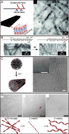
(A) Molecular Structure of a representative peptide amphiphile with four rationally designed chemical entities. (B) Molecular graphics illustration of an this peptide amphiphile molecule and its self-assembly into nanofibers as well as an illustration of the cross-section of these fibers, highlighting the extensive hydration of the peptide shell; (C) TEM micrograph of IKVAV nanofibers; (D) SEM micrograph of IKVAV nanofiber gel network. Reprinted with permission from Niece et al. [15h] (Part C) and Silva et al. [10] (Part D).
Figure 2
Figure 2
(A) Peptide amphiphiles with alternating hydrophobic and hydrophilic amino acid side chains can form flat, wide nanobelts. (B) UV irradiation can be used to transform assemblies from quadruple helical fiber morphology to single fibers by photochemical cleavage of a 2-nitrobenzyl group. (C) Electrostatic repulsion by amino acids in the charged region of the peptide amphiphile can enable transformation from spherical micelles to cylindrical nanofibers upon charge-screening with divalent calcium ions. (D) A phenylalanine-containing PA demonstrating a temporal transformation of nanostructure from twisted ribbons to helical ribbons. Reprinted with permission from: Cui et. al.[28] (Part A), Muraoka et. al.[30a] (Part B), Goldberger et. al.[17d] (Part C), and Pashuck et. al.[31] (Part D)
Figure 3
Figure 3
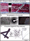
(A) PAs can be used to encapsulate multi-walled carbon nanotubes, simultaneously providing a method for noncovalently functionalizing the surface and enabling dispersion of the carbon nanotubes in an aqueous medium. (B) TEM and electron diffraction showing the crystallographic alignment of hydroxyapatitie nanocrystals that mineralize on PA nanofibers. (C) Demonstration of a method for delivering and controlling the release rate of the cancer drug doxorubicin by enzymatically switching PA assemblies from a cylindrical nanofiber morphology to a disassembled state. Reprinted with permission from: Arnold et. al.[41] (Part A), Spoerke et. al.[43] (Part B) and Webber et. al.[46] (Part C).
Figure 4
Figure 4
(A) Immunohistochemistry of a neural progenitor cell (NPC) neurosphere encapsulated in a laminin-mimetic IKVAV PA gel for 7 days, resulting in extensive neurite outgrowth. β-tubulin labeled green, GFAP labeled red. (B) A higher percentage of NPCs differentiated into neurons (β-tubulin+) in IKVAV PA gels, compared to laminin and poly-d-lysine controls. (C) A smaller percentage of NPCs differentiated into astrocytes (GFAP+) in IKVAV PA gels at 7 days in vitro, compared to laminin and poly-d-lysine controls. Parts A-C adapted with permission from Silva et. al. [10] © AAAS. (D) At 11 weeks following spinal cord injury (SCI), descending motor fibers of mice show regeneration across the lesion in animals receiving IKVAV PA injection 24-hours after injury, but not in control animals. (E) Mean mouse BBB locomotor scores show that IKVAV PA promotes functional recovery from SCI in mice, compared to control animals. Parts D and E reprinted with permission from Tysseling-Mattiace et al. [17c].
Figure 5
Figure 5
Representative images from chicken chorioallantoic membranes stimulated with VEGF mimetic PA compared to controls of VEGF peptide, non-bioactive PA (Mutant PA), and saline. Increased blood vessel density at the site of stimulation is indicative of pro-angiogenic signaling by the VEGF mimetic PA. On the right are images obtained by laser Doppler perfusion imaging of ischemic mouse hindlimbs at the time when ischemia was created (Day 0) and 28 days after administering treatment. Images indicate improved blood flow in the limb with ischemic injury for treatment with VEGF PA compared to controls. Reprinted from Webber et. al. [61]. Copyright © 2011 National Academy of Sciences, USA.
Figure 6
Figure 6
Analysis of the in vivo bone regeneration capacity of collagen scaffolds (Coll) containing heparin-binding peptide amphiphile (HBPA) nanofibers presenting heparin sulfate (HS) and BMP-2. (A) Representative femur reconstructions from micro-computed tomography of the various treatment groups. (B) The number of animals used per condition and the number of animals with a bridged femur after treatment. (C) Quantitative analysis of new bone volume (mm3) within the defect measured by micro-computed tomography. Data are presented as mean ± standard error of the mean; ***P < 0.001. Reprinted with permission from Lee et. al. [71].
Figure 7
Figure 7
Representative histological sections collected 12 weeks after treatment and stained with Safranin-O for glycosaminoglycans (A–D) and type II collagen immunostaining (E–H) in articular cartilage defects treated with (A, E) 100 ng/mL TGF-β1, (B, F) filler PA + 100 ng/mL TGF-β1, (C, G) TGF-β1 binding PA + 100 ng/mL TGF-β1, and (D, H) TGF-β1 binding PA alone. The binding PA with (C, G) and without (D, H) TGF-β1 demonstrating the formation of new cartilage that was histologically similar to existing cartilage. Arrows denote the boundaries of the cartilage defect. Reprinted from Shah et al. [74]. Copyright © 2010 National Academy of Sciences, USA.
Figure 8
Figure 8
(A) A thermally treated peptide amphiphile solution (blue) dragged through a thin layer of aqueous CaCl2 to form a flexible string-like gel. (B) SEM of aligned nanofiber bundles in these string-like gels. (C) Calcein-labeled human mesenchymal stem cells cultured in the aligned nanofibrous gels align in the direction of the fibers. (D) SEM of plaques that were captured by adding CaCl2 to PA solutions at 80 °C and (E) SEM of plaques breaking into nanofiber bundles. (F,G) Schematic representation of a plaque at high temperature (F) and its rupture into fused nanofiber bundles upon cooling of the solution (G). (H) Top: Calcium fluorescence image of HL-1 cardiomyocytes encapsulated in a noodle-like string. Below: Successive spatial maps of calcium fluorescence intensity traveling at 80-ms intervals, showing the propagation of an electrical signal throughout the entire string and demonstrating a functional cardiac syncytium. Figure adapted with permission from Zhang et al. [75] © 2010 Nature Publishing
Figure 9
Figure 9
(A) A schematic representation of a method to form a self-sealing sac by dropping a biopolymer solution into an oppositely charged PA solution. (B) Open and (C) closed sac formation. (D) Self-assembled sacs of varying sizes. (E) An SEM of the cross section of the sac membrane, showing the characteristic layers of the complex assembly process; region 1 is an amorphous layer formed on the side of the membrane with biopolymer, region 2 is a parallel fiber layer rapidly formed at interface between the two solutions, and region 3 is a perpendicular fiber layer that grows as biopolymer diffuses into the PA compartment. (F) Schematic representation of polymer stubs (red) penetrating the diffusion barrier formed at the interface between the two solutions. (G) Subsequent self-assembly of nanofibers (blue) initiated by the stubs. (H) Growth of the nanofibers perpendicular to the interface over time, as the biopolymer diffuses into the PA compartment. Adapted with permission from Capito et. al. [8e] © 2008 AAAS

Similar articles

Cited by

References

    1. Desiraju GR. Nature. 2001;412:397–400. - PubMed
    2. Lehn JM. Chem Soc Rev. 2007;36:151–160. - PubMed
    1. Whitesides GM, Grzybowski B. Science. 2002;295:2418–2421. - PubMed
    2. Stupp SI, LeBonheur VV, Walker K, Li LS, Huggins KE, Keser M, Amstutz A. Science. 1997;276:384–389. - PubMed
    3. Aida T, Meijer EW, Stupp SI. Science. 2012;335:813–817. - PMC - PubMed
    1. Lingwood D, Simons K. Science. 2010;327:46–50. - PubMed
    2. Vereb G, Szollosi J, Matko J, Nagy P, Farkas T, Vigh L, Matyus L, Waldmann TA, Damjanovich S. Proc Natl Acad Sci U S A. 2003;100:8053–8058. - PMC - PubMed
    1. Singer SJ, Nicolson GL. Science. 1972;175:720–731. - PubMed
    1. Johnson JE, Speir JA. J Mol Biol. 1997;269:665–675. - PubMed