. 2014 Mar 4;111(9):3304-9.
doi: 10.1073/pnas.1319878111. Epub 2014 Feb 18.

Liquid metal enabled pump

Affiliations

Liquid metal enabled pump

Shi-Yang Tang et al. Proc Natl Acad Sci U S A. .

Abstract

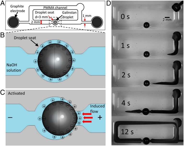
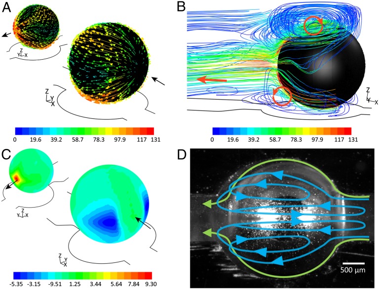
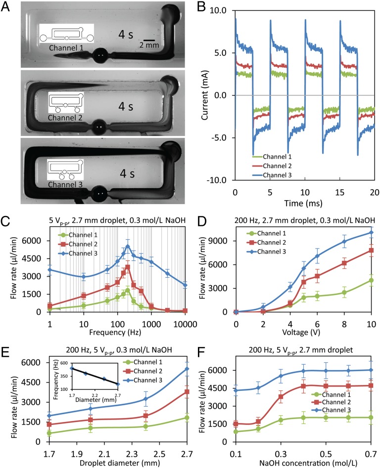
Small-scale pumps will be the heartbeat of many future micro/nanoscale platforms. However, the integration of small-scale pumps is presently hampered by limited flow rate with respect to the input power, and their rather complicated fabrication processes. These issues arise as many conventional pumping effects require intricate moving elements. Here, we demonstrate a system that we call the liquid metal enabled pump, for driving a range of liquids without mechanical moving parts, upon the application of modest electric field. This pump incorporates a droplet of liquid metal, which induces liquid flow at high flow rates, yet with exceptionally low power consumption by electrowetting/deelectrowetting at the metal surface. We present theory explaining this pumping mechanism and show that the operation is fundamentally different from other existing pumps. The presented liquid metal enabled pump is both efficient and simple, and thus has the potential to fundamentally advance the field of microfluidics.


Conflict of interest statement

The authors declare no conflict of interest.

Figures

Fig. 1.
Fig. 1.
Working mechanism of the liquid metal enabled pump. (A) Schematic of the experimental setup, the overall PMMA channel length is 65 mm and the gap between the electrodes is 40 mm. (B) Schematic of the Galinstan droplet surface charge distribution when placed in the droplet chamber filled with NaOH solution. (C) Schematic of the Galinstan droplet surface charge distribution when an electric field is applied between the graphite electrodes. (D) Sequential snapshots for the pumping effect of a Galinstan droplet with 2.7-mm diameter in the PMMA channel filled with NaOH solution (0.3 mol/L), while a square wave signal (200-Hz, 5 Vp-p, 2.5-V DC offset and 50% duty cycle) is applied between the two graphite electrodes. A droplet of dye is used to demonstrate the pumping effect.
Fig. 2.
Fig. 2.
CFD simulation of the liquid metal enabled pump. (A) Flow velocity vectors (millimeters per second) along the droplet surface. (B) Formation of vortices along the droplet surface colored by velocity magnitude of the flow (millimeters per second). (C) Pressure contours along the surface of droplet (pascals) indicating the formation of low-/high-pressure regions at the upstream/downstream hemispheres of the droplet. (D) Trajectory of suspended particles along the top surface of droplet observed from the top by high speed camera.
Fig. 3.
Fig. 3.
Enhancing the pumping flow rate by reducing the distance between the electrodes and characterization of their pumping performance with respect to different parameters. (A) Snapshots of the pumping effect of a Galinstan droplet with 2.7-mm diameter in three PMMA channels, with different electrode spacing, filled with NaOH solution (0.3 mol/L) 4 s after adding a droplet of dye, while a square wave signal (200-Hz, 5 Vp-p, 2.5-V DC offset and 50% duty cycle) is applied between the two graphite electrodes. The schematics of the channels are given in the Insets. (B) Current waveforms, obtained by measuring the voltage across a 1-Ω resistor in series, for the three channels with different electrode gaps under the same square wave signal (using these the powers are obtained by averaging the energy consumed in each cycle). (C) Flow rate vs. square wave frequency plots, obtained with a 2.7-mm diameter Galinstan droplet in a 0.3 mol/L NaOH solution. (D) Flow rate vs. square wave Vp-p plots, obtained with a 2.7-mm diameter Galinstan droplet in a 0.3 mol/L NaOH solution. (E) Flow rate vs. Galinstan droplet diameter plots, obtained within a 0.3 mol/L NaOH solution. Inset shows the optimum working frequency for Galinstan droplet with different sizes. (F) Flow rate vs. liquid NaOH concentration plots, obtained with a 2.7-mm diameter Galinstan droplet. A Vp-p/2 DC offset is always applied to the voltage signals, and the duty cycle of the square wave is 50%.

References

    1. Atencia J, Beebe DJ. Controlled microfluidic interfaces. Nature. 2005;437(7059):648–655. - PubMed
    1. Wu T, et al. A photon-driven micromotor can direct nerve fibre growth. Nat Photonics. 2012;6(1):62–67.
    1. García M, et al. Micromotor-based lab-on-chip immunoassays. Nanoscale. 2013;5(4):1325–1331. - PubMed
    1. Lee J, Kim CJ. Surface-tension-driven microactuation based on continuous electrowetting. J Microelectromech Syst. 2000;9(2):171–180.
    1. Wang C-C, Yao Y-D, Liang K-Y, Huang C-C, Chang Y-C. Development of a miniature fan motor. J Appl Phys. 2012;111(7):07E718.

Publication types