. 2014 Mar;21(Pt 2):340-51.
doi: 10.1107/S160057751400006X. Epub 2014 Feb 4.

D3, the new diffractometer for the macromolecular crystallography beamlines of the Swiss Light Source

Affiliations

D3, the new diffractometer for the macromolecular crystallography beamlines of the Swiss Light Source

Martin R Fuchs et al. J Synchrotron Radiat. 2014 Mar.

Abstract

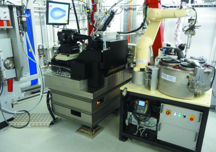
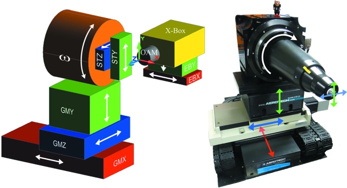
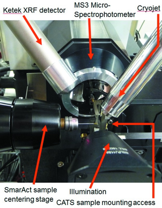
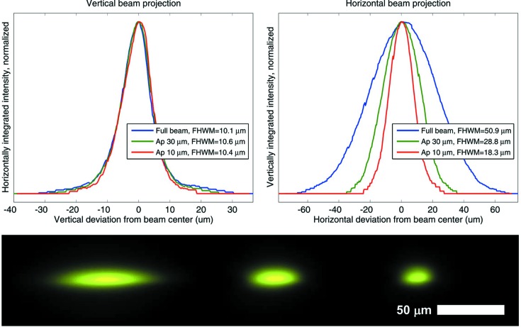
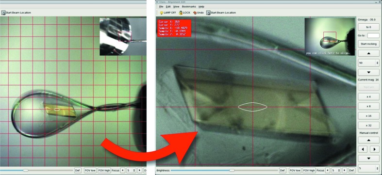
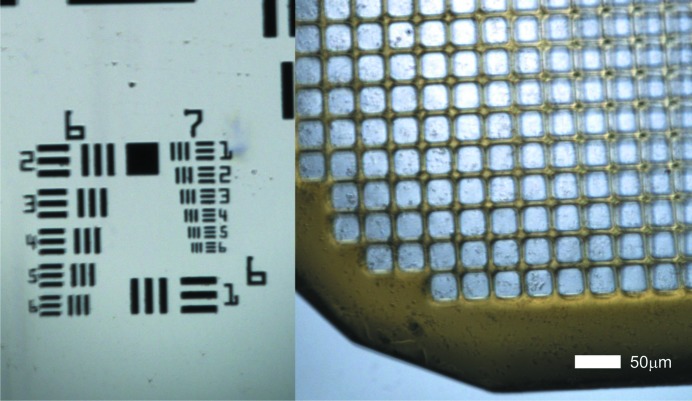
A new diffractometer for microcrystallography has been developed for the three macromolecular crystallography beamlines of the Swiss Light Source. Building upon and critically extending previous developments realised for the high-resolution endstations of the two undulator beamlines X06SA and X10SA, as well as the super-bend dipole beamline X06DA, the new diffractometer was designed to the following core design goals. (i) Redesign of the goniometer to a sub-micrometer peak-to-peak cylinder of confusion for the horizontal single axis. Crystal sizes down to at least 5 µm and advanced sample-rastering and scanning modes are supported. In addition, it can accommodate the new multi-axis goniometer PRIGo (Parallel Robotics Inspired Goniometer). (ii) A rapid-change beam-shaping element system with aperture sizes down to a minimum of 10 µm for microcrystallography measurements. (iii) Integration of the on-axis microspectrophotometer MS3 for microscopic sample imaging with 1 µm image resolution. Its multi-mode optical spectroscopy module is always online and supports in situ UV/Vis absorption, fluorescence and Raman spectroscopy. (iv) High stability of the sample environment by a mineral cast support construction and by close containment of the cryo-stream. Further features are the support for in situ crystallization plate screening and a minimal achievable detector distance of 120 mm for the Pilatus 6M, 2M and the macromolecular crystallography group's planned future area detector Eiger 16M.

Keywords: beamline endstation; diffractometer; macromolecular crystallography; microcrystallography; microspectrophotometer.


Figures

Figure 1
Figure 1
Experimental endstation of beamline X10SA. From left to right: Pilatus 6M area detector (Dectris), D3 diffractometer, CATS robotic sample changer system (IRELEC).
Figure 2
Figure 2
Left: degrees of freedom (DOF) of the D3 diffractometer. The translations GMX, STY and STZ and the rotation ω are used for scanning operations, i.e. with the X-ray shutter opened, the translations GMY and GMZ are used for sample positioning during alignment only. The active X-ray beam feedback to an X-ray beam-position monitor in the so-called exposure box (X-Box) allows the positioning of the beam via the EBX and EBY translations. The on-axis microscope is the reference device to which all others are aligned; the sole DOF with a relation to the microscope is the GMZ translation of the goniometer that is used to bring the sample into focus. Right: DOF mapped onto the actual goniometer.
Figure 3
Figure 3
Vertical deviations of the sample-mounting position during rotations of the stage. The plot shows the integral error contributions of the horizontal air-bearing stage and the sample centering and support mounted on top of the rotation table. (a) Uncorrected error during three successive rotations. (b) Calibration-corrected signal. The average position is marked by the red circle.
Figure 4
Figure 4
Sample environment of the D3 with all devices positioned in closest sample proximity.
Figure 5
Figure 5
(a) Cryo-stream shutter for remotely controlled sample annealing with a pneumatically actuated flexor mechanism. The unit is fabricated in a rapid prototyping polyamide process based on the design by Helmholtz Zentrum Berlin (Mueller et al., 2012 ▶). Left: open position, default. Right: blocking position. The cold stream is diverted to the bottom right direction in the image. (b) Beam-shaping devices, downstream of the reflective objective of the microspectrophotometer. Left: scatter guard collimator, a Mo tube with 0.5 mm outer and 0.3 mm inner diameter, to confine air scatter from the beam up to 5 mm upstream of the sample. Center: triple aperture. Right: data collection configuration with aperture and collimator in the beam.
Figure 6
Figure 6
Top left: vertical beam projections obtained by integrating the intensity at the beam spot in the horizontal direction. Top right: horizontal beam projections. Bottom, from left to right: full beam, and beams through the 30 and 10 µm apertures, imaged by the on-axis sample microscope on a YAG:Ce scintillator screen on the third diagnostic device of the beam-shaping unit.
Figure 7
Figure 7
(a) Beamstop in the parked position, lowered (red arrow) with respect to the sample position (b) at the X-ray beam focus (tip of blue arrow). (c) Carbon blade fixation to beamstop mover via magnets and a reference bracket. Insert: wire-eroded Ag beamstop tip glued to a carbon blade.
Figure 8
Figure 8
Left: measurement set-up for vibrations tests. Signals from accelerometers on the ground are compared with signals from accelerometers on the table (hidden behind the goniometer, see insert). The accelerometers were bolted horizontally via a rigid aluminium L-bracket, or glued vertically directly on the table. Right: comparison of ground vibrations (black line) and vibrations measured concurrently on the diffractometer table (colored line). X is transversal to the beam, Y is vertical and Z is along the beam. Plots of spectral displacement (square root of power spectral density of displacement, formula image
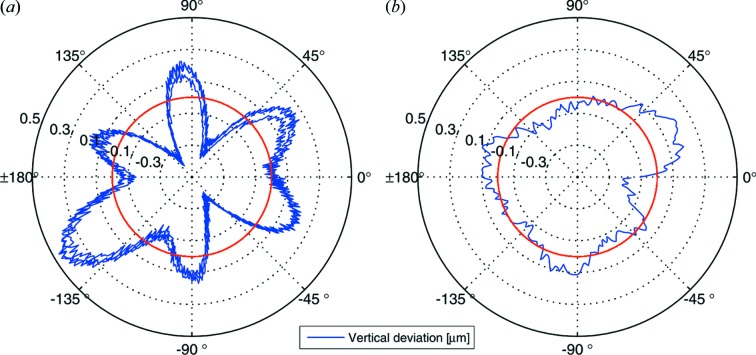
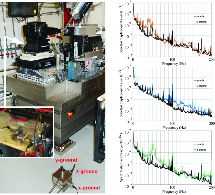
), indicating the lowest vertical eigenfrequency of the table at 40 Hz. In the horizontal directions the width of the 40 Hz resonances extends to approximately 30 Hz.
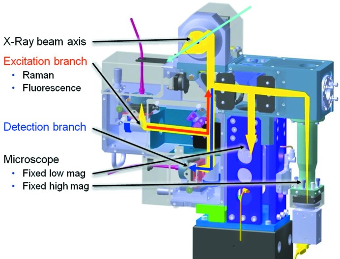
Figure 9
Figure 9
Beam paths of the MS3 microspectrophotometer. All optical axes converge at two beamsplitters underneath the reflective Schwarzschild microscope objective. From there they are deflected on-axis with the X-ray beam by a drilled 45° mirror behind the objective. The imaging branch of the sample-viewing microscope is split by a further beamsplitter into a low-magnification and a high-magnification fixed-zoom branch with separate firewire CCD cameras (Point Grey GRAS-20S4-C). The spectroscopic unit contains the beamsplitter separating the excitation from the detection branch, both coupled via light fibers to various lasers and the spectrographs, respectively.
Figure 10
Figure 10
MS3 microscope image. The two concurrent fixed zoom levels enable the display of a picture-in-picture image. The loop can thus be aligned in the small low-magnification view and the crystal subsequently in the high-magnification main view without having to change zoom levels.
Figure 11
Figure 11
MS3 microscope image resolution. Left: image of a 1951 USAF resolution test pattern conforming to MIL-STD-150A standard. The smallest three-line-pattern, Group 7/Element 6, is still well resolved. It corresponds to a resolution of 228 line pairs per mm, i.e. the width of one line is 2.19 µm. Right: image of a Mitegen MicroMesh (700/25) carrying a suspension of microcrystals of virus spheroids with an average crystal size of 1–2 µm.
Figure 12
Figure 12
Left: ilumination unit of the microspectrophotometer MS3. The unit is a combination of a Köhler-type microscope light and a light guide coupled to an absorption spectroscopy broadband white-light source. A 190 mm vertical translation with a 1 µm resolution permits the unit to be retracted within 2 s. Lateral positioning is provided by the vertical translation and a second horizontal stage (range 10 mm, resolution 1.25 µm). Right: beam paths in the MS3 illumination unit. The vertical beam path of the Köhler illumination comprises (from bottom to top) an LED light source, two lens doublets, an iris to define the illuminated area, a polarizer, a third doublet and a reflective objective. The beam path of the spectroscopic illumination contains the fiber holder, an off-axis parabolic mirror and a beam splitter to couple the light into the reflective objective along with the Köhler illumination branch.

References

    1. Aishima, J., Owen, R. L., Axford, D., Shepherd, E., Winter, G., Levik, K., Gibbons, P., Ashton, A. & Evans, G. (2010). Acta Cryst. D66, 1032–1035. - PMC - PubMed
    1. Alkire, R. W., Duke, N. E. C. & Rotella, F. J. (2008). J. Appl. Cryst. 41, 1122–1133. - PMC - PubMed
    1. Alkire, R. W., Rotella, F. J. & Duke, N. E. C. (2013). J. Appl. Cryst. 46, 525–536. - PMC - PubMed
    1. Ascone, I., Girard, E., Gourhant, P., Legrand, P., Roudenko, O., Roussier, L. & Thompson, A. W. (2007). AIP Conf. Proc. 882, 872–874.
    1. Bingel-Erlenmeyer, R., Olieric, V., Grimshaw, J. P. A., Gabadinho, J., Wang, X., Ebner, S. G., Isenegger, A., Schneider, R., Schneider, J., Glettig, W., Pradervand, C., Panepucci, E. H., Tomizaki, T., Wang, M. & Schulze-Briese, C. (2011). Cryst. Growth Des. 11, 916–923.

Publication types