Editorial
. 2014 Feb 25:11:17.
doi: 10.1186/1743-0003-11-17.

Muscle motor point identification is essential for optimizing neuromuscular electrical stimulation use

Affiliations
Editorial

Muscle motor point identification is essential for optimizing neuromuscular electrical stimulation use

Massimiliano Gobbo et al. J Neuroeng Rehabil. .

Abstract

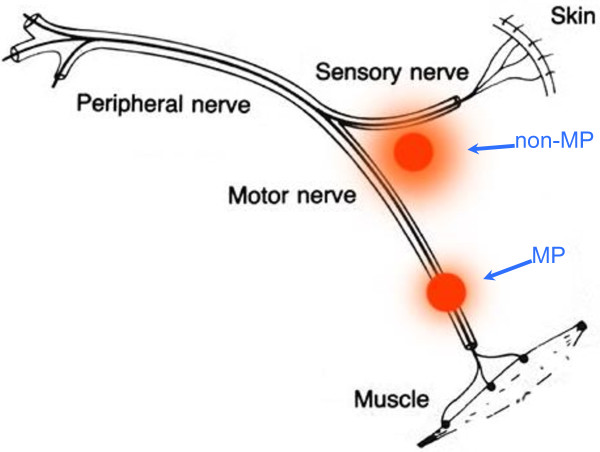
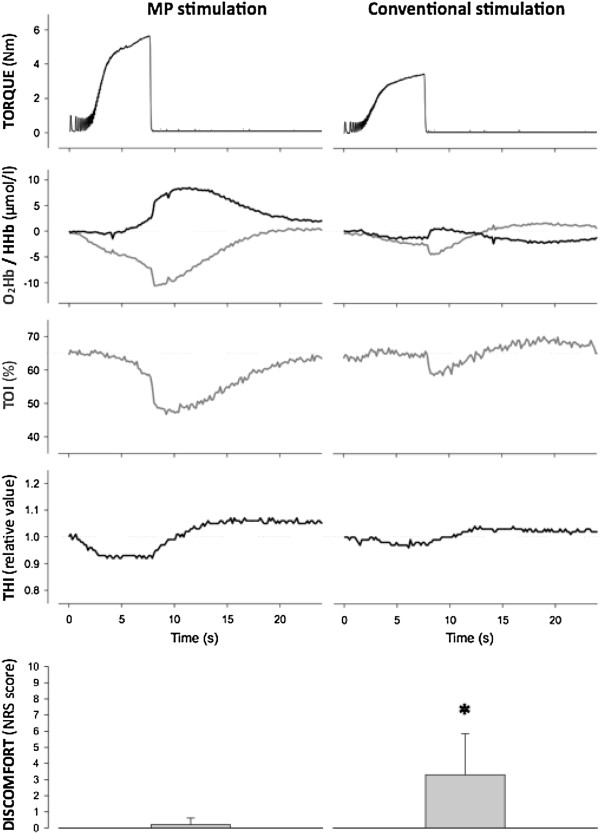
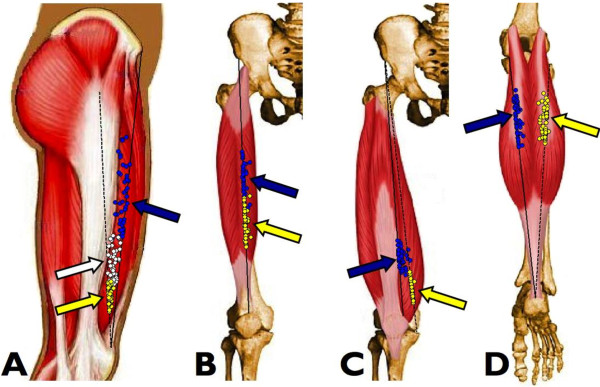
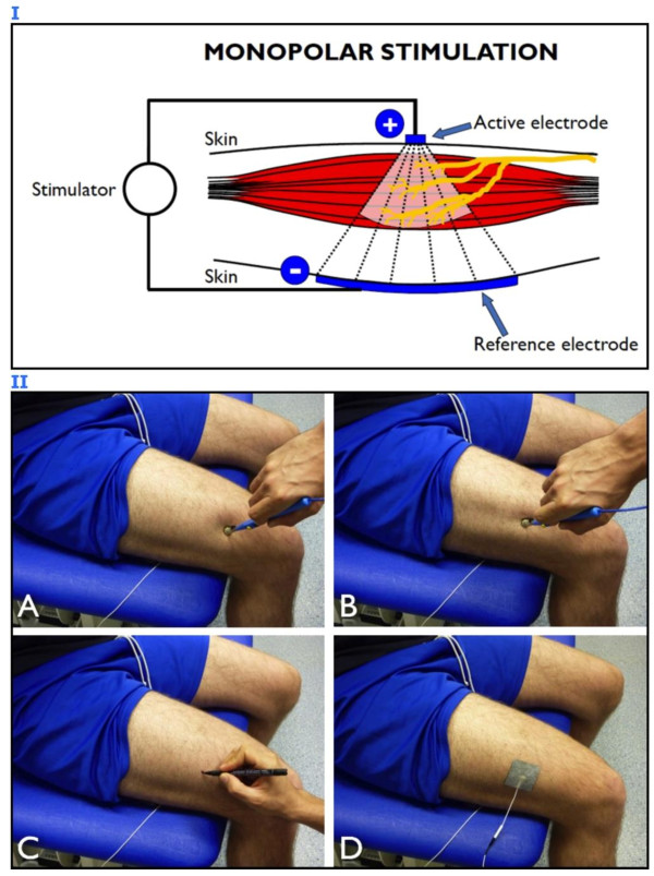
Transcutaneous neuromuscular electrical stimulation applied in clinical settings is currently characterized by a wide heterogeneity of stimulation protocols and modalities. Practitioners usually refer to anatomic charts (often provided with the user manuals of commercially available stimulators) for electrode positioning, which may lead to inconsistent outcomes, poor tolerance by the patients, and adverse reactions. Recent evidence has highlighted the crucial importance of stimulating over the muscle motor points to improve the effectiveness of neuromuscular electrical stimulation. Nevertheless, the correct electrophysiological definition of muscle motor point and its practical significance are not always fully comprehended by therapists and researchers in the field. The commentary describes a straightforward and quick electrophysiological procedure for muscle motor point identification. It consists in muscle surface mapping by using a stimulation pen-electrode and it is aimed at identifying the skin area above the muscle where the motor threshold is the lowest for a given electrical input, that is the skin area most responsive to electrical stimulation. After the motor point mapping procedure, a proper placement of the stimulation electrode(s) allows neuromuscular electrical stimulation to maximize the evoked tension, while minimizing the dose of the injected current and the level of discomfort. If routinely applied, we expect this procedure to improve both stimulation effectiveness and patient adherence to the treatment.The aims of this clinical commentary are to present an optimized procedure for the application of neuromuscular electrical stimulation and to highlight the clinical implications related to its use.


Figures

Figure 1
Figure 1
Schematic representation of a mixed peripheral nerve and two stimulation sites. When the active electrode precisely overlies the motor point (MP), less current is required to excite the motor axons and thus to elicit the muscle contraction. Alternatively, stimulation on the other site (non-MP) requires higher current intensity to reach the motor branch, with possible excitation of the sensory fibers conveying pain.
Figure 2
Figure 2
Torque traces and oxygenation/deoxygenation profiles during neuromuscular electrical stimulation and recovery. The signals, recorded from a representative subject during a frequency ramp contraction (from 2 to 50 Hz in 7.5 s) and the subsequent recovery phase, refer to tibialis anterior muscle stimulation via the motor point (MP stimulation) and stimulation following anatomic reference charts for electrode placement (conventional stimulation). Note that MP stimulation results in greater mechanical stress and metabolic demand than conventional stimulation. O2Hb = oxyhemoglobin; HHb = deoxyhemoglobin; TOI = tissue oxygenation index; THI = total hemoglobin index. The bottom panels are related to subject perception of discomfort evaluated with a numeric rating scale (NRS) and show group mean ± SD values for the two conditions studied in 10 healthy subjects: MP stimulation induces significantly (* P < 0.05) less discomfort than conventional stimulation. NRS scores: 0 = no discomfort; 10 = maximum discomfort. (Modified from Gobbo et al. [6]. Copyright © 2011 Springer. Used with permission provided by Copyright Clearance Center, license number: 2913660233993).
Figure 3
Figure 3
Position of the muscle motor points for the quadriceps and gastrocnemii in 53 healthy subjects. The arrows indicate the average motor point (MP) positions along the respective reference lines. A) Vastus lateralis muscle MPs (blue circles, proximal MP; white circles, central MP; yellow circles, distal MP). The continuous black line is the reference line for the proximal MP, while the dashed black line is the reference line for the central and distal MPs. B) Rectus femoris muscle MPs (blue circles, proximal MP; yellow circles, distal MP). C) Vastus medialis muscle MPs (blue circles, proximal MP; yellow circles, distal MP). The continuous black line is the reference line for the proximal MP, while the dashed black line is the reference line for the distal MP. D) Medial (blue circles) and lateral (yellow circles) gastrocnemii muscle MPs. (Modified from Botter et al. [5]. Copyright © 2011 Springer. Used with permission provided by Copyright Clearance Center, license number: 2923641294715).
Figure 4
Figure 4
Motor point identification procedure. Panel I: schematic representation of monopolar stimulation. The active electrode is placed over the muscle region of interest and the reference electrode is placed over the antagonist muscle or opposite to the active electrode to close the stimulation current loop. Panel II: electrophysiological procedure for motor point (MP) identification and proper electrode placement. The skin surface above the vastus lateralis muscle is mapped with a pen-electrode, the dispersive reference electrode being placed opposite to the active one; the joint angle should be the one adopted for the subsequent stimulation protocol in order to avoid skin displacement with respect to the underlying neural and muscular structures. A) The muscle contractile response is not evident when the pen is not facing the MP area. B) The MP of the target muscle is identified as the specific site where a minimal mechanical response is generated with the lowest current intensity. C) The identified MP is marked with a felt tip. D) The active electrode is placed exactly over the identified MP.

References

    1. Hultman E, Sjöholm H, Jäderholm-Ek I, Krynicki J. Evaluation of methods for electrical stimulation of human skeletal muscle in situ. Pflugers Arch. 1983;398:139–141. doi: 10.1007/BF00581062. - DOI - PubMed
    1. Maffiuletti NA. Physiological and methodological considerations for the use of neuromuscular electrical stimulation. Eur J Appl Physiol. 2010;110:223–234. doi: 10.1007/s00421-010-1502-y. - DOI - PubMed
    1. Walls RJ, McHugh G, O'Gorman DJ, Moyna NM, O'Byrne JM. Effects of preoperative neuromuscular electrical stimulation on quadriceps strength and functional recovery in total knee arthroplasty. A pilot study. BMC Musculoskelet Disord. 2010;11:119. doi: 10.1186/1471-2474-11-119. - DOI - PMC - PubMed
    1. Doucet BM, Lam A, Griffin L. Neuromuscular electrical stimulation for skeletal muscle function. Yale J Biol Med. 2012;85:201–215. - PMC - PubMed
    1. Botter A, Oprandi G, Lanfranco F, Allasia S, Maffiuletti NA, Minetto MA. Atlas of the muscle motor points for the lower limb: implications for electrical stimulation procedures and electrode positioning. Eur J Appl Physiol. 2011;111:2461–2471. doi: 10.1007/s00421-011-2093-y. - DOI - PubMed

Publication types

MeSH terms