. 2014 Apr;13(2):289-302.
doi: 10.1007/s10237-014-0561-0. Epub 2014 Mar 2.

Computational modelling of emboli travel trajectories in cerebral arteries: influence of microembolic particle size and density

Affiliations

Computational modelling of emboli travel trajectories in cerebral arteries: influence of microembolic particle size and density

Dario Fabbri et al. Biomech Model Mechanobiol. 2014 Apr.

Abstract

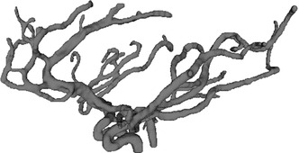
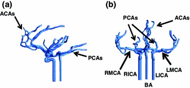
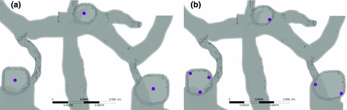
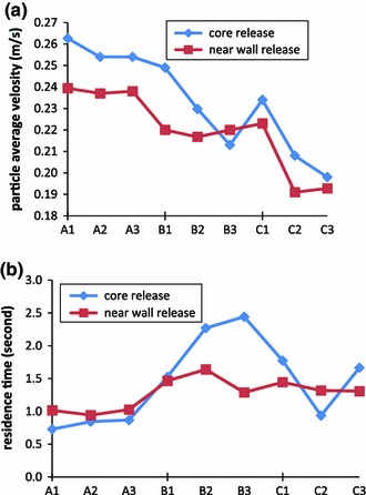
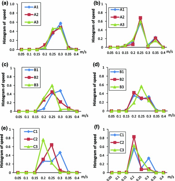
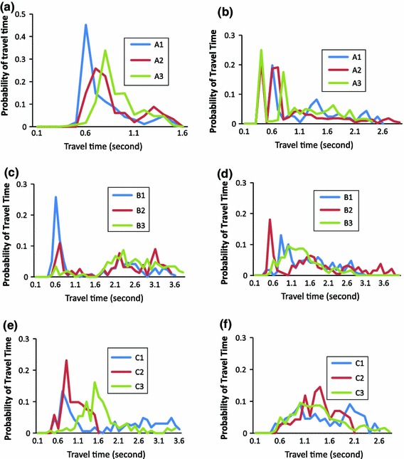
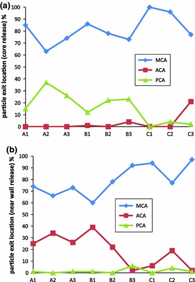
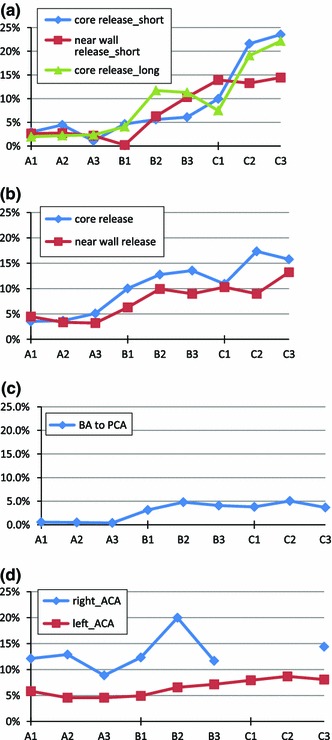
Ischaemic stroke is responsible for up to 80% of stroke cases. Prevention of the reoccurrence of ischaemic attack or stroke for patients who survived the first symptoms is the major treatment target. Accurate diagnosis of the emboli source for a specific infarction lesion is very important for a better treatment for the patient. However, due to the complex blood flow patterns in the cerebral arterial network, little is known so far of the embolic particle flow trajectory and its behaviour in such a complex flow field. The present study aims to study the trajectories of embolic particles released from carotid arteries and basilar artery in a cerebral arterial network and the influence of particle size, mass and release location to the particle distributions, by computational modelling. The cerebral arterial network model, which includes major arteries in the circle of Willis and several generations of branches from them, was generated from MRI images. Particles with diameters of 200, 500 and 800 μm and densities of 800, 1,030 and 1,300 kg/m(3) were released in the vessel's central and near-wall regions. A fully coupled scheme of particle and blood flow in a computational fluid dynamics software ANASYS CFX 13 was used in the simulations. The results show that heavy particles (density large than blood or a diameter larger than 500 μm) normally have small travel speeds in arteries; larger or lighter embolic particles are more likely to travel to large branches in cerebral arteries. In certain cases, all large particles go to the middle cerebral arteries; large particles with higher travel speeds in large arteries are likely to travel at more complex and tortuous trajectories; emboli raised from the basilar artery will only exit the model from branches of basilar artery and posterior cerebral arteries. A modified Circle of Willis configuration can have significant influence on particle distributions. The local branch patterns of internal carotid artery to middle cerebral artery and anterior communicating artery can have large impact on such distributions.


Figures

Fig. 1
Fig. 1
3D surface rendering of the cerebral arterial network
Fig. 2
Fig. 2
Computation model of the cerebral arterial network with extended inlet vessels. a Sagittal view and b coronal view
Fig. 3
Fig. 3
Region selected to release particles in the fully coupled model. Three locations are in the Core flow region (a) and 6 in the Near-wall flow region (b)
Fig. 4
Fig. 4
Influence of particle mass on their motion in cerebral arteries. Particles were released at core location (blue lines) and near-wall locations (red lines): a Average residence times of particles; b average velocity of particles travelling during their path. On x-axis: A, B, C representing particle density of 800, 1,050, 1,300 kg/m3; number 1,2,3 representing particle diameter of 200, 500 and 800 μm as defined in Table 2. (Color figure online)
Fig. 5
Fig. 5
Histogram of particle travel average speed distribution for all particles released in the system for the 9 different particle masses. Panels on the left (a, c, e) are core release cases while panels on the right (b, d, f) are near-wall release cases. In curve labels: A, B, C representing particle density of 800, 1,050, 1,300 kg/m3; number 1,2,3 representing particle diameter of 200, 500 and 800 μm as defined in Table 2
Fig. 6
Fig. 6
Histogram of particle travel time probability for the nine test groups in core release (left panels) and near-wall release cases (right panels). In curve labels: A, B, C representing particle density of 800, 1,050, 1,300 kg/m3; number 1,2,3 representing particle diameter of 200, 500 and 800 μm as defined in Table 2
Fig. 7
Fig. 7
Distributions of particle in the cerebral arteries released from a the central location and b the near-wall locations of both ICAs, for different groups of particles. On x-axis: A, B, C representing particle density of 800, 1,050, 1,300 kg/m3; number 1,2,3 representing particle diameter of 200, 500 and 800 μ as defined in Table 2
Fig. 8
Fig. 8
Tortuosity of particle travelling path in different vessels. a Right ICA to right MCA_1 (short path) and right MCA_2 (long path); b left ICA to left MCA; c BA to left PCA core release only; d right ICA to right ACA (diamond sign) and left ICA to left ACA (rectangular sign), core release only; Due to lack of particle exit to the chosen route for near-wall release, the results of near-wall release cases do not present here for some cases
Fig. 9
Fig. 9
Local geometry of CoW branches. a left side, shows a T junction shape bifurcation from LICA to LMCA and LACoA; b right side, shows a Y shape branch but flow is from RICA to RMCA and RACoA

References

    1. Adboix A, Alio J. Cardioembolic stroke: clinical features, specific cardiac disorders and prognosis. Curr Cardiol Rev. 2010;6:150–161. doi: 10.2174/157340310791658730. - DOI - PMC - PubMed
    1. Ansys CFX User manual (n.d.)
    1. Basciano CA, Kleinstreuer C, Kennedy AS, et al. Computer modelling of controlled microsphere release and targeting in a representative hepatic artery system. Ann Biomed Eng. 2010;38:1862–1879. doi: 10.1007/s10439-010-9955-z. - DOI - PubMed
    1. Bushi D, Grad Y, Einav S, Yodfat O, et al. Hemodynamic evaluation of embolic trajectory in an arterial bifurcation: an in vitro experimental model. Stroke. 2005;36:2696–2700. doi: 10.1161/01.STR.0000190097.08862.9a. - DOI - PubMed
    1. Chung EML, Hague JP, Chanrion MA, et al. Embolus trajectory through a physical replica of the major cerebral arteries. Stroke. 2010;41:647–652. doi: 10.1161/STROKEAHA.109.574400. - DOI - PubMed