

Investigation into image quality and dose for different patient geometries with multiple cone-beam CT systems
- PMID: 24593726
- PMCID: PMC5148045
- DOI: 10.1118/1.4865788
Investigation into image quality and dose for different patient geometries with multiple cone-beam CT systems
Abstract
Purpose: To provide quantitative and qualitative image quality metrics and imaging dose for modern Varian On-board Imager (OBI) (ver. 1.5) and Elekta X-ray Volume Imager (XVI) (ver. 4.5R) cone-beam computed tomography (CBCT) systems in a clinical adaptive radiation therapy environment by accounting for varying patient thickness.
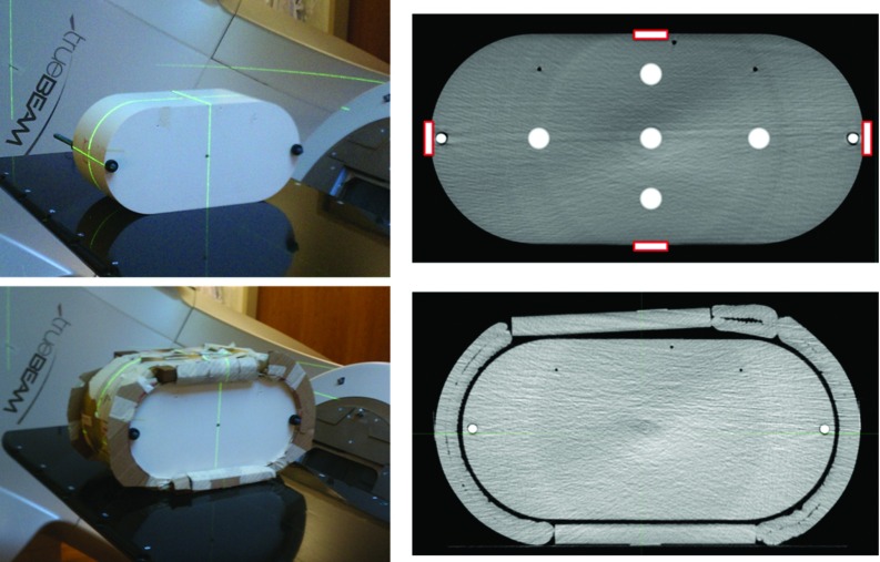
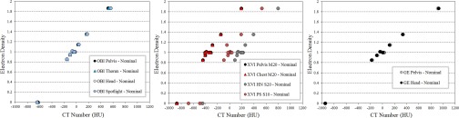
Methods: Image quality measurements were acquired with Catphan 504 phantom (nominal diameter and with additional 10 cm thickness) for OBI and XVI systems and compared to planning CT (pCT) (GE LightSpeed). Various clinical protocols were analyzed for the OBI and XVI systems and analyzed using image quality metrics, including spatial resolution, low contrast detectability, uniformity, and HU sensitivity. Imaging dose measurements were acquired in Wellhofer Scanditronix i'mRT phantom at nominal phantom diameter and with additional 4 cm phantom diameter using GafChromic XRQA2 film. Calibration curves were generated using previously published in-air Air Kerma calibration method.
Results: The OBI system full trajectory scans exhibited very little dependence on phantom thickness for accurate HU calculation, while half-trajectory scans with full-fan filter exhibited dependence of HU calculation on phantom thickness. The contrast-to-noise ratio (CNR) for the OBI scans decreased with additional phantom thickness. The uniformity of Head protocol scan was most significantly affected with additional phantom thickness. The spatial resolution and CNR compared favorably with pCT, while the uniformity of the OBI system was slightly inferior to pCT. The OBI scan protocol dose levels for nominal phantom thickness at the central portion of the phantom were 2.61, 0.72, and 1.88 cGy, and for additional phantom thickness were 1.95, 0.48, and 1.52 cGy, for the Pelvis, Thorax, and Spotlight protocols, respectively. The XVI system scans exhibited dependence on phantom thickness for accurate HU calculation regardless of trajectory. The CNR for the XVI scans decreased with additional phantom thickness. The uniformity of the XVI scans was significantly dependent on the selection of the proper FOV setting for all phantom geometries. The spatial resolution, CNR, and uniformity for XVI were lower than values measured for pCT. The XVI scan protocol dose levels at the central portion of the phantom for nominal phantom thickness were 2.14, 2.15, and 0.33 cGy, and for additional phantom thickness were 1.56, 1.68, and 0.21 cGy, for the Pelvis M20, Chest M20, and Prostate Seed S10 scan protocols, respectively.
Conclusions: The OBI system offered comparable spatial resolution and CNR results to the results for pCT. Full trajectory scans with the OBI system need little-to-no correction for HU calculation based on HU stability with changing phantom thickness. The XVI system offered lower spatial resolution and CNR results than pCT. In addition, the HU calculation for all scan protocols was dependent on the phantom thickness. The uniformity for each CBCT system was inferior to that of pCT for each phantom geometry. The dose for each system and scan protocol in the interior of the phantom tended to decrease by approximately 25% with 4 cm additional phantom thickness.
Figures


References
-
- Zhong R., Wang J., Jiang X., He Y., Zhang H., Chen N., Bai S., and Xu F., “Hypofraction radiotherapy of liver tumor using cone beam computed tomography guidance combined with active breath control by long breath-holding,” Radiot. Oncol. 104, 379–385 (2012).10.1016/j.radonc.2011.11.007 - DOI - PubMed
-
- Nakagawa K., Yamashita H., Shiraishi K., Igaki H., Terahara A., Nakamura N., Ohtomo K., Saegusa S., Shiraki T., and Oritate T., “Verification of in-treatment tumor position using kilovoltage cone-beam computed tomography: A preliminary study,” Int. J. Radiat. Oncol., Biol., Phys. 69, 970–973 (2007).10.1016/j.ijrobp.2007.08.026 - DOI - PubMed
-
- Smitsmans M. H., De Bois J., Sonke J., Betgen A., Zijp L. J., Jaffray D. A., Lebesque J. V., and van Herk M., “Automatic prostate localization on cone-beam CT scans for high precision image-guided radiotherapy,” Int. J. Radiat. Oncol., Biol., Phys. 63, 975–984 (2005).10.1016/j.ijrobp.2005.07.973 - DOI - PubMed
-
- Purdie T. G., Moseley D. J., Bissonnette J., Sharpe M. B., Franks K., Bezjak A., and Jaffray D. A., “Respiration correlated cone-beam computed tomography and 4DCT for evaluating target motion in stereotactic lung radiation therapy,” Acta Oncol. 45, 915–922 (2006).10.1080/02841860600907345 - DOI - PubMed
Publication types
MeSH terms
Substances
Grants and funding
LinkOut - more resources
Full Text Sources
Other Literature Sources
Medical
