Comparative Study
. 2014 Sep;84(5):830-8.
doi: 10.2319/092513-702.1. Epub 2014 Mar 10.

An analytical approach to 3D orthodontic load systems

Affiliations
Comparative Study

An analytical approach to 3D orthodontic load systems

Thomas R Katona et al. Angle Orthod. 2014 Sep.

Abstract

Objective: To present and demonstrate a pseudo three-dimensional (3D) analytical approach for the characterization of orthodontic load (force and moment) systems.

Materials and methods: Previously measured 3D load systems were evaluated and compared using the traditional two-dimensional (2D) plane approach and the newly proposed vector method.

Results: Although both methods demonstrated that the loop designs were not ideal for translatory space closure, they did so for entirely different and conflicting reasons.

Conclusions: The traditional 2D approach to the analysis of 3D load systems is flawed, but the established 2D orthodontic concepts can be substantially preserved and adapted to 3D with the use of a modified coordinate system that is aligned with the desired tooth translation.

Keywords: Biomechanics; Moment-to-force ratio; Orthodontic force systems; T-loop archwire; Three-dimensional.


Figures

Figure 1. (a) Occlusal view of the simulated clinical case showing the global (X-Y) and the estimated local (x-y) coordinate systems on the maxillary lateral incisor (approximately 30°) and the canine (approximately 65°) brackets. (b) The x-y-z axes of the lateral incisor bracket.
Figure 1.
(a) Occlusal view of the simulated clinical case showing the global (X-Y) and the estimated local (x-y) coordinate systems on the maxillary lateral incisor (approximately 30°) and the canine (approximately 65°) brackets. (b) The x-y-z axes of the lateral incisor bracket.
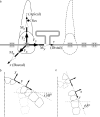
Figure 2. (a) Schematic of complete generic load system acting on a maxillary left lateral incisor bracket. ±Fx, ±Fy, and ±Fz force components act in the buccal/palatal, distal/mesial, and apical/incisal directions, respectively. The directions of the moment vector components (±Mx, ±My, and ±Mz) are defined by the RHR convention—the thumb of the right hand points in the direction of the moment (open) vector arrow, and the fingers indicate the direction of rotation. As an example, −Mz would produce a mesial-in distal-out rotation. (b) The distorted arch corresponds to the depictions in Figure 2a and in Figure 1a. (c) Distorted arch based on canine x-y data.
Figure 2.
(a) Schematic of complete generic load system acting on a maxillary left lateral incisor bracket. ±Fx, ±Fy, and ±Fz force components act in the buccal/palatal, distal/mesial, and apical/incisal directions, respectively. The directions of the moment vector components (±Mx, ±My, and ±Mz) are defined by the RHR convention—the thumb of the right hand points in the direction of the moment (open) vector arrow, and the fingers indicate the direction of rotation. As an example, −Mz would produce a mesial-in distal-out rotation. (b) The distorted arch corresponds to the depictions in Figure 2a and in Figure 1a. (c) Distorted arch based on canine x-y data.
Figure 3. Load systems required for distal translation applied at (a) CRes or at (b and c) the bracket. b and c use, respectively, the RHR and the more (dentally) conventional depictions.
Figure 3.
Load systems required for distal translation applied at (a) CRes or at (b and c) the bracket. b and c use, respectively, the RHR and the more (dentally) conventional depictions.
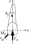
Figure 4. For translation, Mx also counters the second order rotation produced by Fz.
Figure 4.
For translation, Mx also counters the second order rotation produced by Fz.
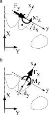
Figure 5. Mz  =  −Fydx + Fxdy to prevent rotations produced by (a) Fy and (b) Fx.
Figure 5.
Mz  =  −Fydx + Fxdy to prevent rotations produced by (a) Fy and (b) Fx.
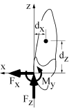
Figure 6. My is applied to prevent third order rotation produced by Fx and Fz in the x-z plane. My  =  Fxdz + Fzdx.
Figure 6.
My is applied to prevent third order rotation produced by Fx and Fz in the x-z plane. My  =  Fxdz + Fzdx.
Figure 7. Each force component can generate two moment components. Each moment component can be generated by two force components.
Figure 7.
Each force component can generate two moment components. Each moment component can be generated by two force components.
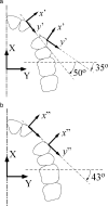
Figure 8. (a) Instead of traditional analyses in the two x-y coordinate systems (Figures 1 through 6), it is proposed that analyses be performed in the two x′-y′ systems in which the y′-axes are more closely aligned (approximately 50° instead of approximately 30° for the incisor and approximately 35° instead of approximately 65° for the premolar) with the direction of desired tooth translations. (b) Analogous to Figure 2a, the assumption that the two y′-axes are collinear yields the y″-axis. Its angulation, 43°, is the average of the 35° and the 50°. (Alternatively, the 43° approximates the line joining the two brackets.) With this approximation, the gross arch distortion (Figure 2b) is avoided, and the traditional widely accepted concepts associated with Figure 2a are more acceptable.
Figure 8.
(a) Instead of traditional analyses in the two x-y coordinate systems (Figures 1 through 6), it is proposed that analyses be performed in the two x′-y′ systems in which the y′-axes are more closely aligned (approximately 50° instead of approximately 30° for the incisor and approximately 35° instead of approximately 65° for the premolar) with the direction of desired tooth translations. (b) Analogous to Figure 2a, the assumption that the two y′-axes are collinear yields the y″-axis. Its angulation, 43°, is the average of the 35° and the 50°. (Alternatively, the 43° approximates the line joining the two brackets.) With this approximation, the gross arch distortion (Figure 2b) is avoided, and the traditional widely accepted concepts associated with Figure 2a are more acceptable.
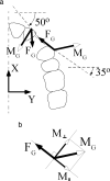
Figure 9. (a) For the desired tooth translations, each FG must approximate its y′-axis. With an appropriate FG, as on the canine for example, to counteract its tipping action, (b) there must be a component of MG, M⊥, which is perpendicular to the force. M∥ is the component of MG that is parallel to FG.
Figure 9.
(a) For the desired tooth translations, each FG must approximate its y′-axis. With an appropriate FG, as on the canine for example, to counteract its tipping action, (b) there must be a component of MG, M, which is perpendicular to the force. M is the component of MG that is parallel to FG.
Figure 10. Traditional presentation of force and moment components on the brackets produced by the first loop design. The results for 0, 1, and 2 mm of activations on the (a and b) incisor and (d and e) canine.
Figure 10.
Traditional presentation of force and moment components on the brackets produced by the first loop design. The results for 0, 1, and 2 mm of activations on the (a and b) incisor and (d and e) canine.
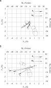
Figure 11. The same data as in Figure 10, but as vectors (FG and MG) projected onto the occlusal plane for the (a) incisor and (b) canine. The 0, 1, and 2 indicate activations in mm.
Figure 11.
The same data as in Figure 10, but as vectors (FG and MG) projected onto the occlusal plane for the (a) incisor and (b) canine. The 0, 1, and 2 indicate activations in mm.
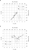
Figure 12. As in Figure 11 but for the second loop design.
Figure 12.
As in Figure 11 but for the second loop design.

References

    1. Chen J, Bulucea I, Katona TR, Ofner S. Complete orthodontic load systems on teeth in a continuous full archwire: the role of triangular loop position. Am J Orthod Dentofacial Orthop. 2007;132:143.e141–148. - PubMed
    1. Chen J, Markham DL, Katona TR. Effects of T-loop geometry on its forces and moments. Angle Orthod. 2000;70:48–51. - PubMed
    1. Gregg J, Chen J. The effect of wire fixation methods on the measured loading systems of a T-loop orthodontics spring. Paper presented at: AAO Annual Meeting; May, 1997; Philadelphia, Pa.
    1. Katona TR, Le YP, Chen J. The effects of first- and second-order gable bends on forces and moments generated by triangular loops. Am J Orthod Dentofacial Orthop. 2006;129:54–59. - PubMed
    1. Lisniewska-Machorowska B, Cannon J, Williams S, Bantleon HP. Evaluation of force systems from a “free-end” force system. Am J Orthod Dentofacial Orthop. 2008;133:791.e1–10. - PubMed

Publication types

LinkOut - more resources