. 2014 Mar;19(3):36009.
doi: 10.1117/1.JBO.19.3.036009.

Three-dimensional, distendable bladder phantom for optical coherence tomography and white light cystoscopy

Affiliations

Three-dimensional, distendable bladder phantom for optical coherence tomography and white light cystoscopy

Kristen L Lurie et al. J Biomed Opt. 2014 Mar.

Abstract

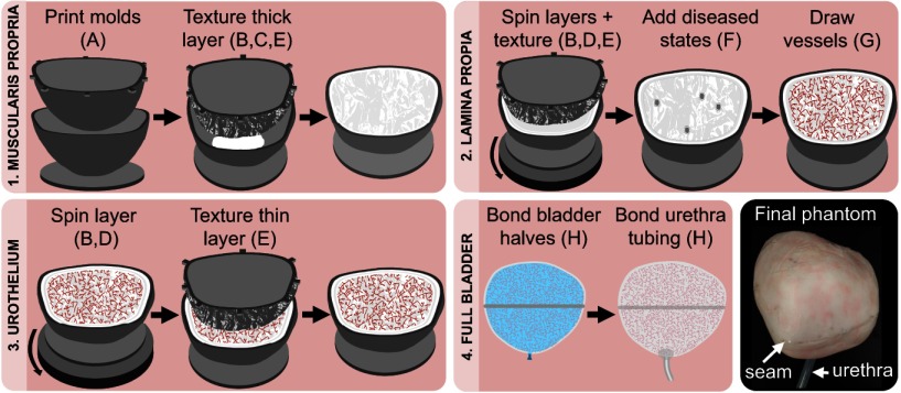
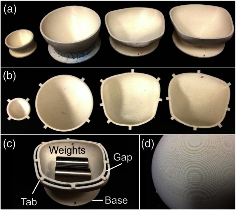
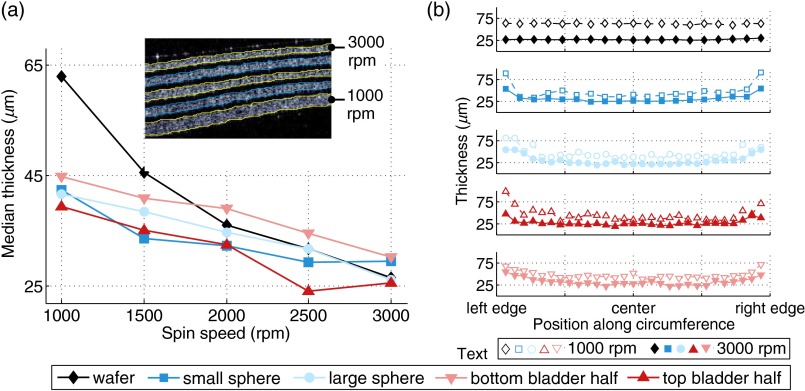
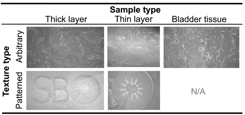
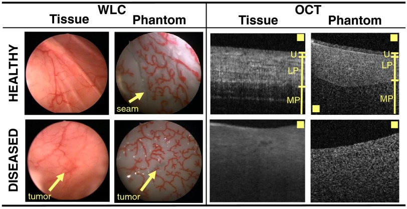
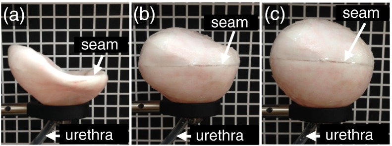
We describe a combination of fabrication techniques and a general process to construct a three-dimensional (3-D) phantom that mimics the size, macroscale structure, microscale surface topology, subsurface microstructure, optical properties, and functional characteristics of a cancerous bladder. The phantom also includes features that are recognizable in white light (i.e., the visual appearance of blood vessels), making it suitable to emulate the bladder for emerging white light+optical coherence tomography (OCT) cystoscopies and other endoscopic procedures of large, irregularly shaped organs. The fabrication process has broad applicability and can be generalized to OCT phantoms for other tissue types or phantoms for other imaging modalities. To this end, we also enumerate the nuances of applying known fabrication techniques (e.g., spin coating) to contexts (e.g., nonplanar, 3-D shapes) that are essential to establish their generalizability and limitations. We anticipate that this phantom will be immediately useful to evaluate innovative OCT systems and software being developed for longitudinal bladder surveillance and early cancer detection.


Figures

Fig. 1
Fig. 1
Representative steps to fabricate a full-bladder phantom. The sequence of steps 1 to 3 is performed twice—once for each half of the bladder—before step 4. Letters refer to techniques listed in Table 1.
Fig. 2
Fig. 2
Collection of molds we tested: (a) Outer molds and (b) corresponding inner molds for the 50-mm sphere, 100-mm sphere, top half of bladder, and bottom half of bladder. (c) Visualization of the gap for sandwich molding (shows the flat base, alignment tabs, and positioning of weights used during molding). (d) Closeup of the textured surface of the molds caused by the finite resolution of the three-dimensional (3-D) printer.
Fig. 3
Fig. 3
Physical thickness of spin-coated layers. (a) Median layer thickness versus spin speed for five 3-D shapes. The inset shows a representative OCT-B-scan of multiple layers fabricated on the bottom half of the bladder at different spin speeds. (b) Layer thickness versus spin speed and normalized distance along shape diameter (wafer) or circumference (molds).
Fig. 4
Fig. 4
Examples of thick and thin layers (left and middle columns, respectively) textured by embossing with crumpled foil (top row) or a mold patterned with our laboratory logo “SBO” (bottom row). An image of bladder tissue is presented for comparison with foil embossing (right column). All images are presented in grayscale.
Fig. 5
Fig. 5
White light cystoscopy (WLC) (Video 1) and optical coherence tomography (OCT) comparisons of bladder tissue and the bladder phantom. The boxes in OCT-B-scans are 100  μm2. Individual layers in healthy B-scans are labeled: urothelium (U), lamina propria (LP), and muscularis propria (MP). Note that the WLC and OCT images are not collected from the same locations (MOV, 8.3 MB) [URL: http://dx.doi.org/10.1117/1.JBO.19.3.036009.1]..
Fig. 6
Fig. 6
Exterior of bladder phantom undergoing distention with various air pressures (Video 2): (a) hypodistention, (b) normal distention, and (c) hyperdistention. Grid boxes are approximately 20×20  mm2 (MOV, 4.1 MB) [URL: http://dx.doi.org/10.1117/1.JBO.19.3.036009.2].

References

    1. Li X. D., et al. , “Optical coherence tomography: advanced technology for the endoscopic imaging of Barrett’s esophagus,” Endoscopy 32(12), 921–930 (2000).ENDCAM10.1055/s-2000-9626 - DOI - PubMed
    1. Adler D. C., et al. , “Three-dimensional endomicroscopy using optical coherence tomography,” Nat. Photonics 1(12), 709–716 (2007).10.1038/nphoton.2007.228 - DOI
    1. Brand S., et al. , “Optical coherence tomography in the gastrointestinal tract,” Endoscopy 32(10), 796–803 (2000).ENDCAM10.1055/s-2000-7714 - DOI - PubMed
    1. Shen B., Zuccaro G., “Optical coherence tomography in the gastrointestinal tract,” Gastrointest. Endosc. 14(3), 555–571 (2004).GAENBQ10.1016/j.giec.2004.03.007 - DOI - PubMed
    1. Lerner S. P., et al. , “Optical coherence tomography as an adjunct to white light cystoscopy for intravesical real-time imaging and staging of bladder cancer,” Urology 72(1), 133–137 (2008).10.1016/j.urology.2008.02.002 - DOI - PubMed

Publication types

MeSH terms