. 2014 Mar 1;53(3):403-412.
doi: 10.1007/s00466-013-0968-y.

Computational modeling of magnetic nanoparticle targeting to stent surface under high gradient field

Affiliations

Computational modeling of magnetic nanoparticle targeting to stent surface under high gradient field

Shunqiang Wang et al. Comput Mech. .

Abstract

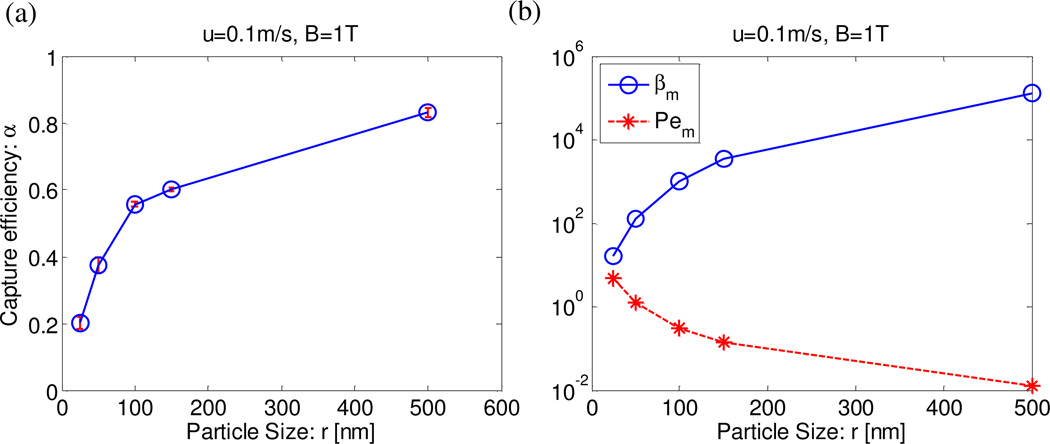
A multi-physics model was developed to study the delivery of magnetic nanoparticles (MNPs) to the stent-implanted region under an external magnetic field. The model is firstly validated by experimental work in literature. Then, effects of external magnetic field strength, magnetic particle size, and flow velocity on MNPs' targeting and binding have been analyzed through a parametric study. Two new dimensionless numbers were introduced to characterize relative effects of Brownian motion (BM), magnetic force induced particle motion, and convective blood flow on MNPs motion. It was found that larger magnetic field strength, bigger MNP size, and slower flow velocity increase the capture efficiency of MNPs. The distribution of captured MNPs on the vessel along axial and azimuthal directions was also discussed. Results showed that the MNPs density decreased exponentially along axial direction after one-dose injection while it was uniform along azimuthal direction in the whole stented region (averaged over all sections). For the beginning section of the stented region, the density ratio distribution of captured MNPs along azimuthal direction is center-symmetrical, corresponding to the center-symmetrical distribution of magnetic force in that section. Two different generation mechanisms are revealed to form four main attraction regions. These results could serve as guidelines to design a better magnetic drug delivery system.

Keywords: magnetic force; magnetic nano-particles; magnetic stent; particle size; targeted delivery.


Figures

Fig. 1
Fig. 1
Setup of the system: a Palmaz-Schatz type of stent is embedded in a blood vessel. A uniform magnetic field along Z direction is applied in the system. MNPs are released from the inlet. The size unit is millimeter.
Fig. 2
Fig. 2
Capture efficiency for stents of various relative permeability, with u=0.2 m/s and r=350 nm. The inset shows the normalized capture efficiency, which is defined as ratio of capture efficiency to that in the reference case of μr=1.8. Solid line represents experimental results in Forbe's work and dashed line represents numerical results. Error bars stand for standard error.
Fig. 3
Fig. 3
(a) Flow velocity distribution across the channel. The flow velocity ranges from 0 m/s to 0.7 m/s as indicated by the color bar; (b) Cross section view of flow velocity; (c) Magnetic flux density distribution across the system. The magnetic flux density ranges from 1.4 T to 3.04 T as shown in the color bar; (d) Cross section view of magnetic field
Fig. 4
Fig. 4
(a) Capture efficiency under various magnetic fields, with u=0.1 m/s and r=100 nm. The inset magnifies the results under the magnetic field of 0 T and 0.01 T; (b) βm and Pem in terms of magnetic fields under the same situation as (a)
Fig. 5
Fig. 5
(a) Capture efficiency of particle of various sizes, with u=0.1 m/s and B=1 T; (b) βm and Pem in terms of particle sizes under the same situation as (a)
Fig. 6
Fig. 6
(a) Capture efficiency under various flow velocities, with r=100 nm and B=1 T; (b) βm and Pem in terms of flow velocities under the same situation as (a)
Fig. 7
Fig. 7
(a) Distribution of captured MNPs (dots in the figure) in the vessel (only MNPs and stents are shown). The capture ratio decreases from inlet (left) to outlet (right). (b) Cross section view of the distribution of captured MNPs. (c) Normalized capture ratio of MNPs along the axial direction. The inset shows the stented region is divided into 10 equal regions in the axial direction, numbering from 1 to 10. (d) Normalized capture ratio of MNPs along azimuthal direction. The inset shows the cross-section region is also divided into 10 equal sections along azimuthal direction.
Fig. 8
Fig. 8
(a) Magnetic force distribution in the beginning section of the stented region. Arrows show the magnitude and direction of the magnetic force near the inner channel surface. (b) Ratio distribution of captured MNPs in the azimuthal direction. The blue bold dashed line illustrates the normalized value of capture ratio of MNPs in the section of stented regions. The circular dashed line marks zero ratio of captured MNPs. The stent struts are corresponded in two views using dot-dash lines. In order to make the figure more concise, the stent is plotted partially.

Similar articles

Cited by

References

    1. Chen GJ, Wang LF. Design of magnetic nanoparticles-assisted drug delivery system. Current pharmaceutical design. 2011;17(22):2331–2351. - PubMed
    1. Yigit MV, Moore A, Medarova Z. Magnetic Nanoparticles for Cancer Diagnosis and Therapy. Pharm Res-Dordr. 2012;29(5):1180–1188. - PMC - PubMed
    1. Azhar SL, Lotfipour F. Magnetic nanoparticles for antimicrobial drug delivery. Die Pharmazie. 2012;67(10):817–821. - PubMed
    1. Park H, Yang J, Seo S, Kim K, Suh J, Kim D, Haam S, Yoo KH. Multifunctional nanoparticles for photothermally controlled drug delivery and magnetic resonance imaging enhancement. Small. 2008;4(2):192–196. - PubMed
    1. Dave SR, Gao X. Monodisperse magnetic nanoparticles for biodetection, imaging, and drug delivery: a versatile and evolving technology. Wiley interdisciplinary reviews Nanomedicine and nanobiotechnology. 2009;1(6):583–609. - PubMed

LinkOut - more resources