

Chemically grafted fibronectin for use in QCM-D cell studies
- PMID: 24657645
- PMCID: PMC3997653
- DOI: 10.1016/j.bios.2014.02.053
Chemically grafted fibronectin for use in QCM-D cell studies
Abstract
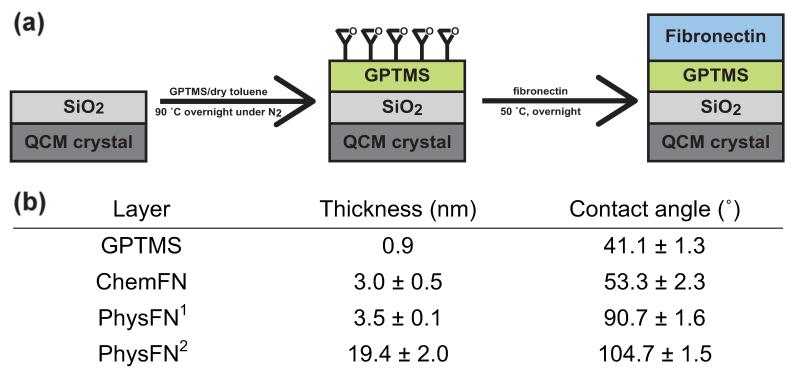
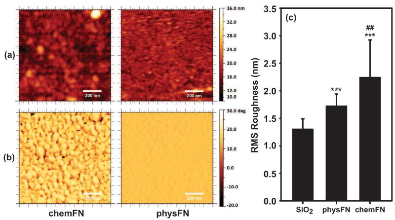
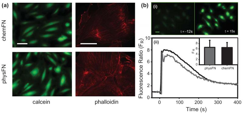
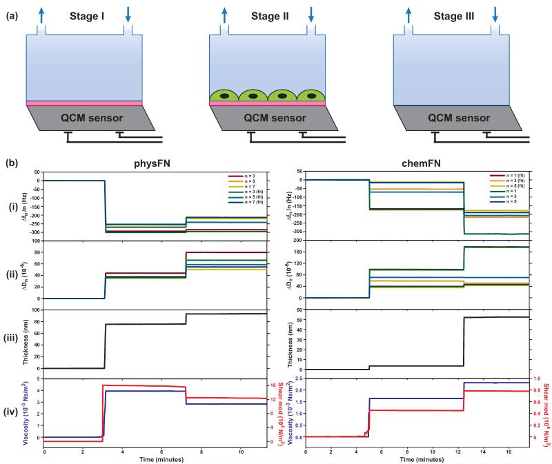
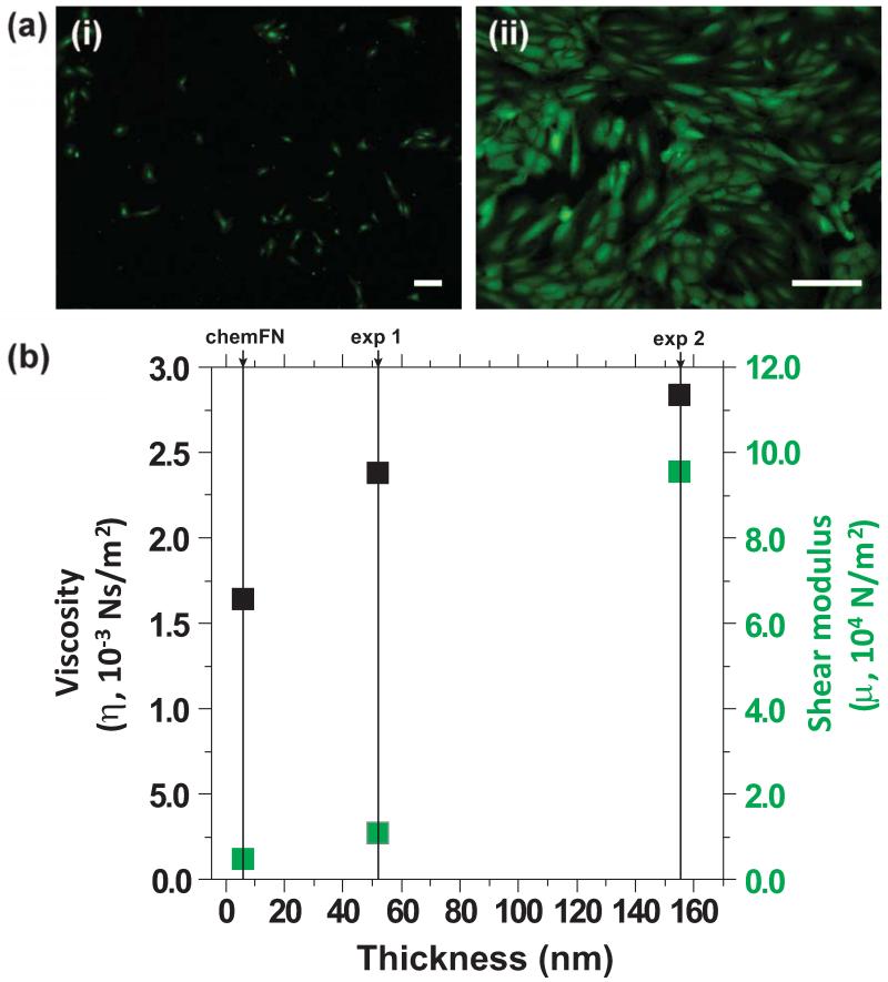
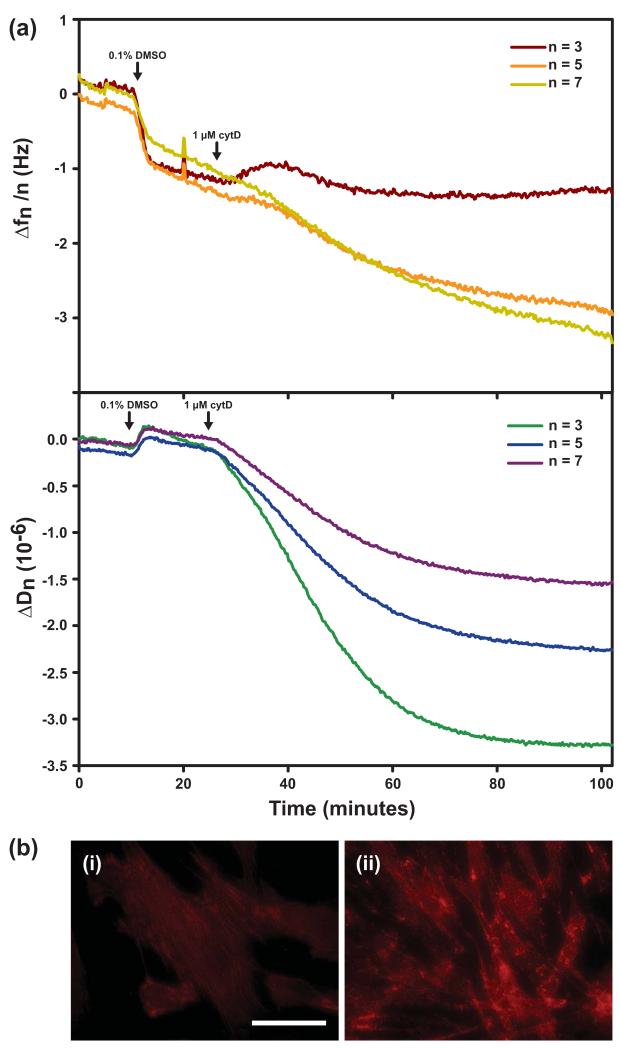
Traditionally, fibronectin has been used as a physisorbed surface coating (physFN) in cell culture experiments due to its critical role in cell adhesion. However, because the resulting layer is thick, unstable, and of unpredictable uniformity, this method of fibronectin deposition is unsuitable for some types of research, including quartz crystal microbalance (QCM) experiments involving cells. Here, we present a new method for chemical immobilization of fibronectin onto silicon oxide surfaces, including QCM crystals pre-coated with silicon oxide. We characterize these chemically coated fibronectin surfaces (chemFN) as well as physFN ones using spectroscopic ellipsometry (SE), Fourier transform infrared spectroscopy (FTIR), atomic force microscopy (AFM), and contact angle measurements. A cell culture model demonstrates that cells on chemFN and physFN surfaces exhibit similar viability, structure, adhesion and metabolism. Finally, we perform QCM experiments using cells on both surfaces which demonstrate the superior suitability of chemFN coatings for QCM research, and provide real-time QCM-D data from cells subjected to an actin depolymerizing agent. Overall, our method of chemical immobilization of fibronectin yields great potential for furthering cellular experiments in which thin, stable and uniform coatings are desirable. As QCM research with cells has been rather limited in success thus far, we anticipate that this new technique will particularly benefit this experimental system by availing it to the much broader field of cell mechanics.
Keywords: Biocompatibility; Cell mechanics; Endothelial cells; Fibronectin; Quartz crystal microbalance; Surface coating.
Copyright © 2014 Elsevier B.V. All rights reserved.
Figures
Similar articles
-
Monitoring cell adhesion on tantalum and oxidised polystyrene using a quartz crystal microbalance with dissipation.Biomaterials. 2006 Sep;27(26):4529-37. doi: 10.1016/j.biomaterials.2006.04.006. Epub 2006 May 22. Biomaterials. 2006. PMID: 16716396
-
Comparison of selective attachment and growth of smooth muscle cells on gelatin- and fibronectin-coated micropatterns.J Nanosci Nanotechnol. 2005 Nov;5(11):1809-15. doi: 10.1166/jnn.2005.436. J Nanosci Nanotechnol. 2005. PMID: 16433414
-
The effect of silica nanoparticulate coatings on serum protein adsorption and cellular response.Biomaterials. 2006 Oct;27(28):4856-62. doi: 10.1016/j.biomaterials.2006.05.037. Epub 2006 Jun 6. Biomaterials. 2006. PMID: 16757021
-
Acoustic detection of cell adhesion to a coated quartz crystal microbalance - implications for studying the biocompatibility of polymers.Biotechnol J. 2013 Jun;8(6):690-8. doi: 10.1002/biot.201200320. Epub 2013 Apr 11. Biotechnol J. 2013. PMID: 23447442
-
Analytical Techniques for the Characterization of Bioactive Coatings for Orthopaedic Implants.Biomedicines. 2021 Dec 17;9(12):1936. doi: 10.3390/biomedicines9121936. Biomedicines. 2021. PMID: 34944750 Free PMC article. Review.
Cited by
-
Guiding Fibroblast Activation Using an RGD-Mutated Heparin Binding II Fragment of Fibronectin for Gingival Titanium Integration.Adv Healthc Mater. 2023 Aug;12(21):e2203307. doi: 10.1002/adhm.202203307. Epub 2023 May 10. Adv Healthc Mater. 2023. PMID: 37100430 Free PMC article.
-
Automated detection of whole-cell mitochondrial motility and its dependence on cytoarchitectural integrity.Biotechnol Bioeng. 2015 Jul;112(7):1395-405. doi: 10.1002/bit.25563. Epub 2015 Mar 13. Biotechnol Bioeng. 2015. PMID: 25678368 Free PMC article.
-
Quartz Crystal Microbalance With Dissipation Monitoring: A Powerful Method to Predict the in vivo Behavior of Bioengineered Surfaces.Front Bioeng Biotechnol. 2018 Oct 30;6:158. doi: 10.3389/fbioe.2018.00158. eCollection 2018. Front Bioeng Biotechnol. 2018. PMID: 30425985 Free PMC article. Review.
-
Targeted release of tobramycin from a pH-responsive grafted bilayer challenged with S. aureus.Biomacromolecules. 2015 Feb 9;16(2):650-9. doi: 10.1021/bm501751v. Epub 2015 Jan 27. Biomacromolecules. 2015. PMID: 25585173 Free PMC article.
-
De Novo Design of Integrin α5β1 Modulating Proteins to Enhance Biomaterial Properties.Adv Mater. 2025 Aug;37(34):e2500872. doi: 10.1002/adma.202500872. Epub 2025 Jun 9. Adv Mater. 2025. PMID: 40489013 Free PMC article.
References
-
- Bacakova L, Filova E, Parizek M, Ruml T, Svorcik V. Biotechnology Advances. 2011;29:739–767. - PubMed
-
- Campoccia D, Montanaro L, Arciola CR. Biomaterials. 2013;34:8533–8554. - PubMed
-
- Chen JY, Shahid A, Garcia MP, Penn LS, Xi J. Biosensors and Bioelectronics. 2012;38:375–381. - PubMed
-
- Cheng S-S, Chittur KK, Sukenik CN, Culp LA, Lewandowska K. Journal of Colloid and Interface Science. 1994;162:135–143.
Publication types
MeSH terms
Substances
Grants and funding
LinkOut - more resources
Full Text Sources
Other Literature Sources
Research Materials
Miscellaneous
