

Two-dimensional imaging in a lightweight portable MRI scanner without gradient coils
- PMID: 24668520
- PMCID: PMC4257909
- DOI: 10.1002/mrm.25147
Two-dimensional imaging in a lightweight portable MRI scanner without gradient coils
Abstract
Purpose: As the premiere modality for brain imaging, MRI could find wider applicability if lightweight, portable systems were available for siting in unconventional locations such as intensive care units, physician offices, surgical suites, ambulances, emergency rooms, sports facilities, or rural healthcare sites.
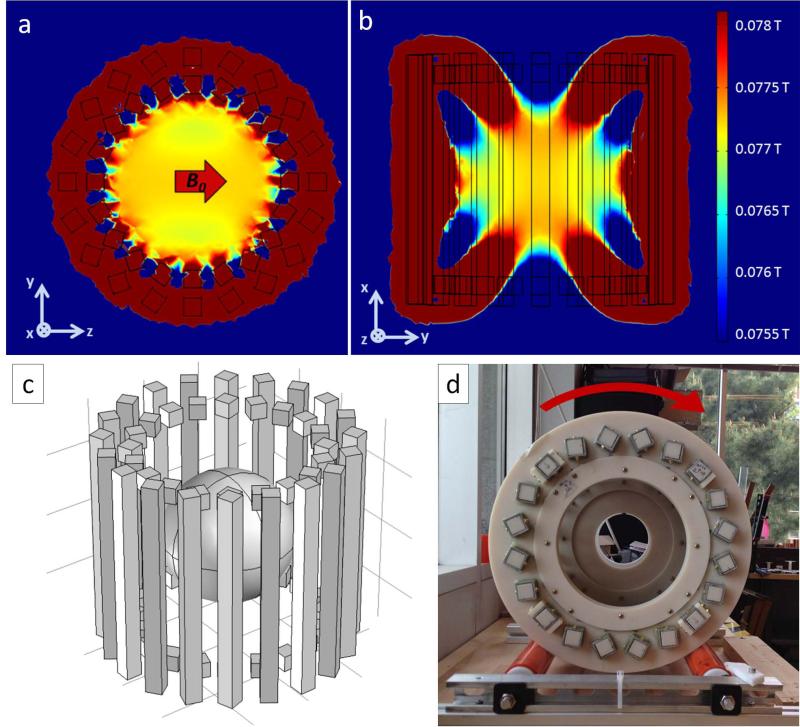
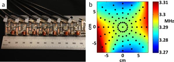
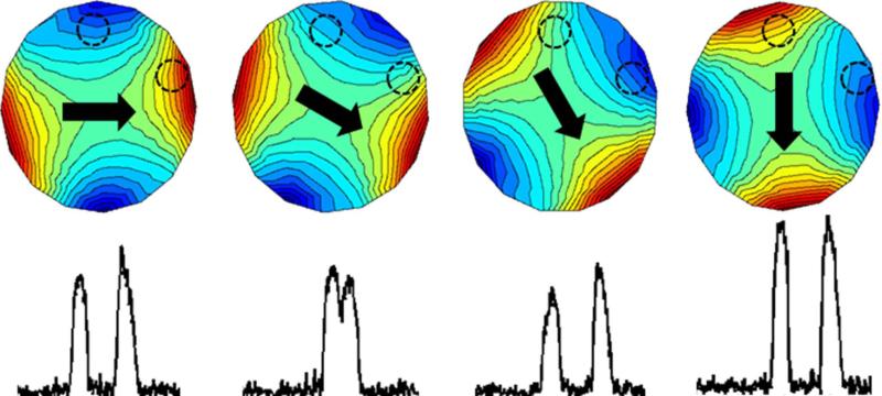
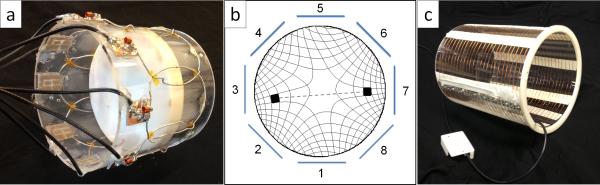
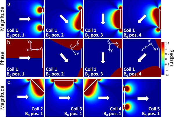
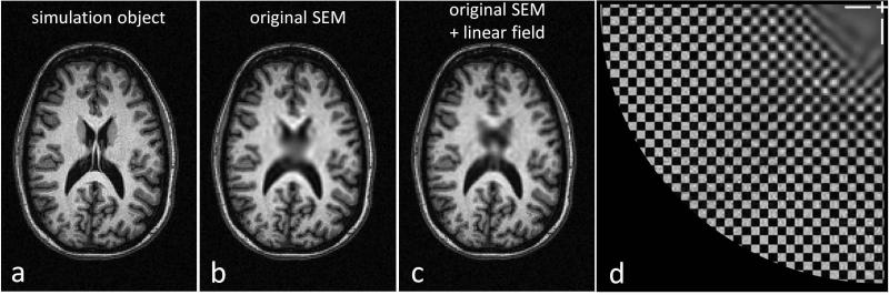
Methods: We construct and validate a truly portable (<100 kg) and silent proof-of-concept MRI scanner which replaces conventional gradient encoding with a rotating lightweight cryogen-free, low-field magnet. When rotated about the object, the inhomogeneous field pattern is used as a rotating spatial encoding magnetic field (rSEM) to create generalized projections which encode the iteratively reconstructed two-dimensional (2D) image. Multiple receive channels are used to disambiguate the nonbijective encoding field.
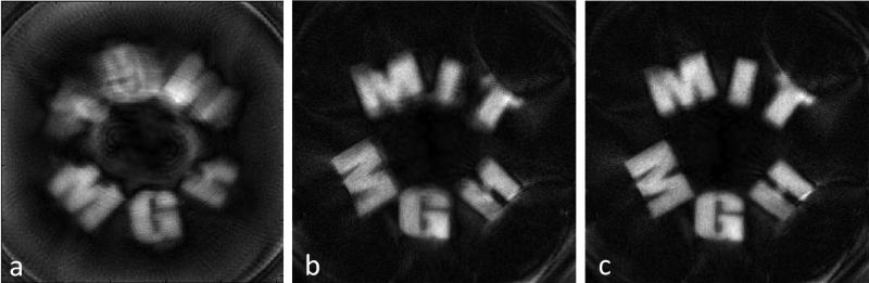
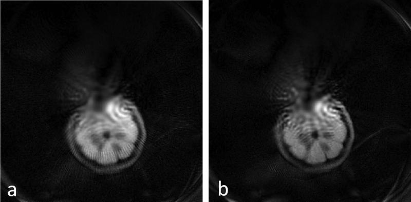
Results: The system is validated with experimental images of 2D test phantoms. Similar to other nonlinear field encoding schemes, the spatial resolution is position dependent with blurring in the center, but is shown to be likely sufficient for many medical applications.
Conclusion: The presented MRI scanner demonstrates the potential for portability by simultaneously relaxing the magnet homogeneity criteria and eliminating the gradient coil. This new architecture and encoding scheme shows convincing proof of concept images that are expected to be further improved with refinement of the calibration and methodology.
Keywords: Halbach magnet; low-field MRI; nonlinear SEMs; parallel imaging; portable MRI.
© 2014 Wiley Periodicals, Inc.
Figures
Similar articles
-
Low-cost and portable MRI.J Magn Reson Imaging. 2020 Sep;52(3):686-696. doi: 10.1002/jmri.26942. Epub 2019 Oct 12. J Magn Reson Imaging. 2020. PMID: 31605435 Free PMC article. Review.
-
Transmit Array Spatial Encoding (TRASE) using broadband WURST pulses for RF spatial encoding in inhomogeneous B0 fields.J Magn Reson. 2016 Jul;268:36-48. doi: 10.1016/j.jmr.2016.04.005. Epub 2016 Apr 8. J Magn Reson. 2016. PMID: 27155906 Free PMC article.
-
PexLoc-Parallel excitation using local encoding magnetic fields with nonlinear and nonbijective spatial profiles.Magn Reson Med. 2013 Nov;70(5):1220-8. doi: 10.1002/mrm.24559. Epub 2012 Nov 30. Magn Reson Med. 2013. PMID: 23203228
-
Multi-slice MRI with the dynamic multi-coil technique.NMR Biomed. 2015 Nov;28(11):1526-34. doi: 10.1002/nbm.3414. Epub 2015 Sep 30. NMR Biomed. 2015. PMID: 26419649 Free PMC article.
-
The technological future of 7 T MRI hardware.NMR Biomed. 2016 Sep;29(9):1305-15. doi: 10.1002/nbm.3315. Epub 2015 May 14. NMR Biomed. 2016. PMID: 25974894 Review.
Cited by
-
Recent advances in microresonators and supporting instrumentation for electron paramagnetic resonance spectroscopy.Rev Sci Instrum. 2022 Oct 1;93(10):101101. doi: 10.1063/5.0097853. Rev Sci Instrum. 2022. PMID: 36319314 Free PMC article.
-
Low-cost and portable MRI.J Magn Reson Imaging. 2020 Sep;52(3):686-696. doi: 10.1002/jmri.26942. Epub 2019 Oct 12. J Magn Reson Imaging. 2020. PMID: 31605435 Free PMC article. Review.
-
Multi-parametric optimization of magnetic resonance imaging sequences for magnetic resonance-guided radiotherapy.Phys Imaging Radiat Oncol. 2023 Oct 2;28:100497. doi: 10.1016/j.phro.2023.100497. eCollection 2023 Oct. Phys Imaging Radiat Oncol. 2023. PMID: 37869476 Free PMC article.
-
Low-field MRI: Clinical promise and challenges.J Magn Reson Imaging. 2023 Jan;57(1):25-44. doi: 10.1002/jmri.28408. Epub 2022 Sep 19. J Magn Reson Imaging. 2023. PMID: 36120962 Free PMC article. Review.
-
Radiology 2040.Radiology. 2023 Jan;306(1):69-72. doi: 10.1148/radiol.222594. Radiology. 2023. PMID: 36534608 Free PMC article.
References
-
- Kose K, Haishi T. High resolution NMR imaging using a high field yokeless permanent magnet. Magn Reson Med Sci. 2011;10:159–167. - PubMed
-
- Kimura T, Geya Y, Terada Y, Kose K, Haishi T, Gemma H, Sekozawa Y. Development of a mobile magnetic resonance imaging system for outdoor tree measurements. Rev Sci Instrum. 2011;82:053704. - PubMed
-
- Gerlach R, du Mesnil de Rochemont R, Gasser T, Marquardt G, Reusch J, Imoehl L, Seifert V. Feasibility of Polestar N20, an ultra-low-field intraoperative magnetic resonance imaging system in resection control of pituitary macroadenomas: lessons learned from the first 40 cases. Neurosurgery. 2008;63:272–284. discussion 284–285. - PubMed
-
- Jackson JA, Burnett LJ, Harmon JF. Remote (inside-out) NMR. III. Detection of nuclear magnetic resonance in a remotely produced region of homogeneous magnetic field. J Magn Reson. 1980;41:411–421.
-
- Sagawa M, Fujimura S, Togawa N, Yamamoto H, Matsuura Y. New material for permanent magnets on a base of Nd and Fe (invited). J. Appl. Phys. 1984;55:2083–2087.
Publication types
MeSH terms
Grants and funding
LinkOut - more resources
Full Text Sources
Other Literature Sources
Medical
Research Materials
