Clinical Trial
. 2014 Oct;3(10):1597-607.
doi: 10.1002/adhm.201400073. Epub 2014 Mar 26.

Multifunctional skin-like electronics for quantitative, clinical monitoring of cutaneous wound healing

Affiliations
Clinical Trial

Multifunctional skin-like electronics for quantitative, clinical monitoring of cutaneous wound healing

Yoshiaki Hattori et al. Adv Healthc Mater. 2014 Oct.

Abstract

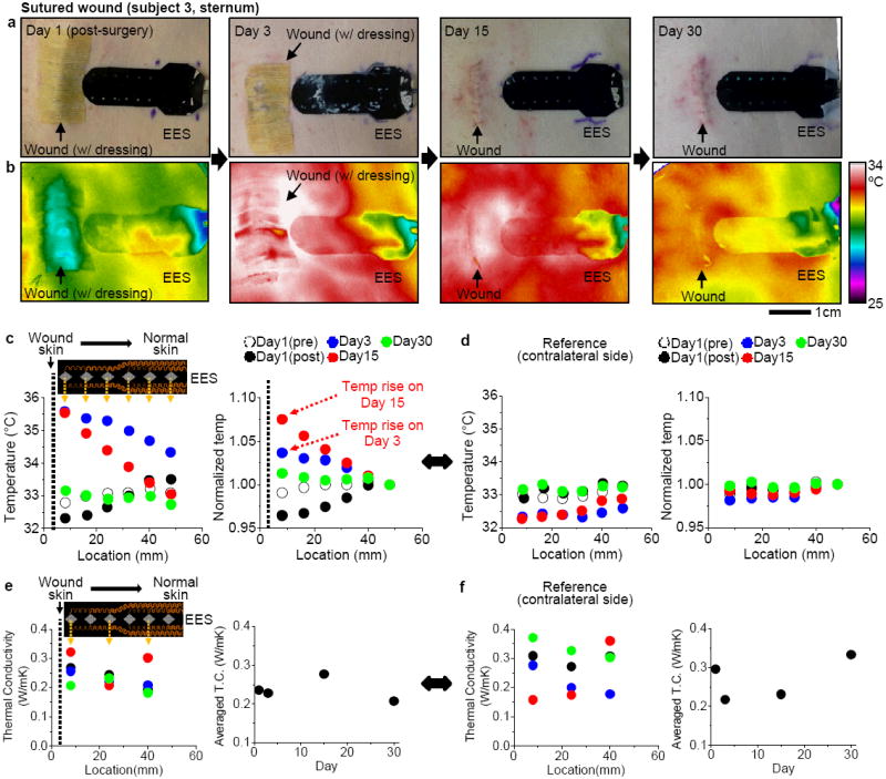
Non-invasive, biomedical devices have the potential to provide important, quantitative data for the assessment of skin diseases and wound healing. Traditional methods either rely on qualitative visual and tactile judgments of a professional and/or data obtained using instrumentation with forms that do not readily allow intimate integration with sensitive skin near a wound site. Here, an electronic sensor platform that can softly and reversibly laminate perilesionally at wounds to provide highly accurate, quantitative data of relevance to the management of surgical wound healing is reported. Clinical studies on patients using thermal sensors and actuators in fractal layouts provide precise time-dependent mapping of temperature and thermal conductivity of the skin near the wounds. Analytical and simulation results establish the fundamentals of the sensing modalities, the mechanics of the system, and strategies for optimized design. The use of this type of "epidermal" electronics system in a realistic clinical setting with human subjects establishes a set of practical procedures in disinfection, reuse, and protocols for quantitative measurement. The results have the potential to address important unmet needs in chronic wound management.

Keywords: clinical study; epidermal electronics; multifunctional; skin-like; wound monitoring.


Figures

Figure 1
Figure 1
Device design and mechanics modeling. (a) Schematic illustration of an EES. (b) Image of an device under uniaxial stretching , multimodal folding (c) and biaxial stretching and twisting (d) and 720° twisting (e). (f) Top view and tilted view (g) microXCT images of the device in (d). (h) FEM analysis and experimental study of a fractal construct under uniaxial stretching; FEM (top) and experiment (bottom). The inset in the middle illustrates the neutral mechanical plane (NMP) of the metal with polyimide (PI) encapsulation.
Figure 2
Figure 2
Multifunctional characteristics. (a) Data acquisition system. (b) Parameters of the lock-in amplifier for measurement of temperature and thermal conductivity. (c) Electrical resistance of six sensors in an EES, as a function of surface temperature. (d) Measurement of thermal conductivity by an EES. (e) Simulation of the oscillating temperature distribution induced in the skin by the EES. (f) IR thermography during Joule heating (35 mA) using one of the sensors in the EES as a micro-heater. (g) Simulation of the rise in temperature on the surface of the device upon Joule heating (35 mA). (h) Simulation of the rise in temperature on the skin tissue on the device surface upon Joule heating.
Figure 3
Figure 3
Device characterization. (a) Effect of mechanical stretching on the measured temperature. (b) Effect of bending on the measured temperature. (c) IR thermogram of the forearm with an EES mounted. (d) Temperature distribution on the skin measured by the IR camera and the EES along blue dotted line shown in (c). The horizontal axis shows the distance from the top of the heater. (e) EES mounted on the forearm with a wet paper towel that covers sensor #3. (f) Distribution of measured thermal conductivity of the skin. The value from sensor #3 shows a clear, expected difference from the other sensors. (g) Thermal conductivity of air, 50% ethanol and acrylic sheet measured after multiple cycles of cleaning. The straight lines in the graph show the actual values. (h) Thermal conductivity measured on the forearm with 20 measurements in one individual.
Figure 4
Figure 4
Use of an EES on human subjects in a clinical setting. (a) EES laminated on the skin (forearm) after sterilization. (b) Microscope images of the skin with thirty attempts of mounting and removal of an EES. (c) Microscope image of the skin after the medical tape removal (1) and image of the tape surface (2). (d) Illustration of the materials interface between the EES and skin (e) Illustration between the medical tape and skin. (f) Fluorescence images of viability of skin cells grown on an EES (left) and the control on the regular cell culture materials (right). Most of cells on the EES remain viable (‘red’ cells). (g) Clinical setting for wound monitoring in a typical exam room. (h) EES laminated on wound and contralateral (control) sites. (i) Assessment sequence and estimated time.
Figure 5
Figure 5
Quantitative monitoring of a granulating wound with an EES. (a) Representative photos of the wound with an EES from day 1 to day 30. (b) Corresponding IR images of the temperature distribution associated with (a). (c) Temperature distribution recorded with an EES (inset) from wound skin to normal skin during one month. The six sensors span a distance of 45 mm in lateral direction. (d) Temperature distribution on a contralateral side. (e) Thermal conductivity (T.C.) distribution recorded with three sensors in an EES (inset). (f) Thermal conductivity (T.C.) on a contralateral side as a control.
Figure 6
Figure 6
Quantitative management of sutured wound with an EES. (a) Representative photos of the wound with an EES from day 1 to day 30. (b) Corresponding IR images of the temperature distribution associated with (a). (c) Temperature distribution recorded with an EES (inset) from wound skin to normal skin during one month. The six sensors span a distance of 45 mm in lateral direction. (d) Temperature distribution on a contralateral side. (e) Thermal conductivity (T.C.) distribution recorded with three sensors in an EES (inset). (f) Thermal conductivity (T.C.) on a contralateral side as a control.

References

    1. Dargaville TR, Farrugia BL, Broadbent JA, Pace S, Upton Z, Voelcker NH. Biosens Bioelectron. 2013;41:30. - PubMed
    1. Panuncialman J, Hammerman S, Carson P, Falanga V. J Invest Dermatol. 2009;129:S47.
    1. Hess CT, Kirsner RS. Advan Skin Wound Care. 2003;16:246. - PubMed
    1. Lange-Asschenfeldt S, Bob A, Terhorst D, Ulrich M, Fluhr J, Mendez G, Roewert-Huber HJ, Stockfleth E, Lange-Asschenfeldt B. J Biomed Opt. 2012;17:076016. - PubMed
    1. Crane NJ, Elster EA. J Biomed Opt. 2012;17:010902. - PubMed

Publication types