. 2014 Jun;7(2):89-95.
doi: 10.1007/s12178-014-9218-y.

Mechanical, Anatomical, and Kinematic Axis in TKA: Concepts and Practical Applications

Affiliations

Mechanical, Anatomical, and Kinematic Axis in TKA: Concepts and Practical Applications

Jeffrey J Cherian et al. Curr Rev Musculoskelet Med. 2014 Jun.

Abstract

Successful total knee arthroplasty (TKA) has often been based on the restoration of the knee to neutral alignment postoperatively. Numerous reports have linked malaligned TKA components to increased wear, poor functional outcomes, and failure. There have been many different alignment philosophies and surgical techniques that have been established to attain the goal of proper alignment, which includes such techniques as computerized navigation, and custom cutting guides. In addition, these methods could potentially have the added benefit of leading to improved functional outcomes following total knee arthroplasty. In this report, we have reviewed and analyzed recent reports concerning mechanical, anatomic, and kinematic axis/alignment schemes used in total knee arthroplasty.


Figures

Fig. 1
Fig. 1
Long-leg standing radiograph demonstrating the mechanical axis of the lower extremity (MA), mechanical axis of the femur (MA), and anatomic axis of the femur and tibia (AA). The angle between the MAF and AAF is typically between 5° and 7°. The joint line forms an angle (α) that is 93° with the MAT, or 3°of varus
Fig. 2
Fig. 2
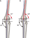
Example of 2 different knee alignment schemes. Anatomic alignment (a) attempts to mimic the natural knee by cutting the tibia at 3° varus to the mechanical axis of the tibia and a distal femoral cut that is 9° valgus to the mechanical axis of the femur to recreate a 6° valgus joint line. Mechanical alignment (b) involves a tibial cut that is perpendicular to the mechanical axis of the tibia and a distal femoral cut 6° valgus to the anatomic axis (perpendicular to the mechanical axis) of the femur

References

    1. Blumenfeld TJ. CORR Insights (R): is TKA using patient-specific instruments comparable to conventional TKA? A randomized controlled study of one system. Clin Orthop Relat Res. 2013;471:3996. doi: 10.1007/s11999-013-3283-1. - DOI - PMC - PubMed
    1. Barrett WP, Mason JB, Moskal JT, Dalury DF, Oliashirazi A, Fisher DA. Comparison of radiographic alignment of imageless computer-assisted surgery vs conventional instrumentation in primary total knee arthroplasty. J Arthroplasty. 2011;26:1273. doi: 10.1016/j.arth.2011.04.037. - DOI - PubMed
    1. D'Lima DD, Chen PC, Colwell CW., Jr Polyethylene contact stresses, articular congruity, and knee alignment. Clin Orthop Relat Res. 2001;392:232. doi: 10.1097/00003086-200111000-00029. - DOI - PubMed
    1. Pickering S, Armstrong D. Focus on alignment in total knee replacement. J Bone Joint Surg. 2012. http://www.boneandjoint.org.uk/content/focus/alignment-total-knee-replac.... Accessed 15 Jan 2014.
    1. D'Lima DD, Hermida JC, Chen PC, Colwell CW., Jr Polyethylene wear and variations in knee kinematics. Clin Orthop Relat Res. 2001;392:124. doi: 10.1097/00003086-200111000-00015. - DOI - PubMed