. 2008 Jan 1:2008:23-32.
doi: 10.1145/1394281.1394285.

Misperceptions in Stereoscopic Displays: A Vision Science Perspective

Affiliations

Misperceptions in Stereoscopic Displays: A Vision Science Perspective

Robert T Held et al. ACM Trans Graph. .

Abstract

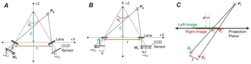
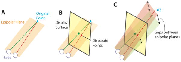
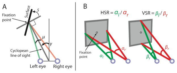
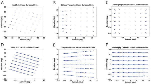
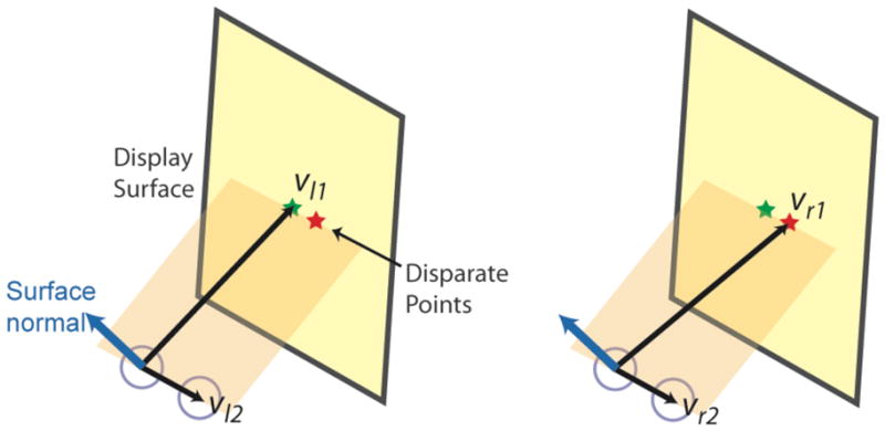
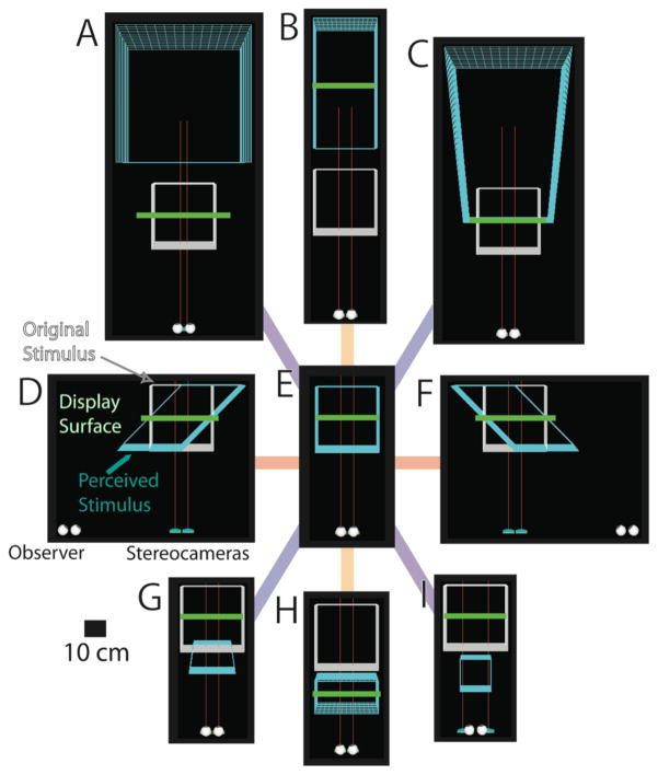
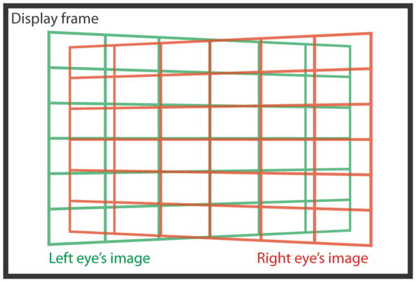
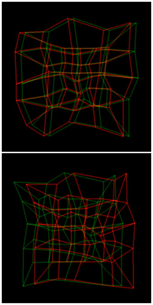
3d shape and scene layout are often misperceived when viewing stereoscopic displays. For example, viewing from the wrong distance alters an object's perceived size and shape. It is crucial to understand the causes of such misperceptions so one can determine the best approaches for minimizing them. The standard model of misperception is geometric. The retinal images are calculated by projecting from the stereo images to the viewer's eyes. Rays are back-projected from corresponding retinal-image points into space and the ray intersections are determined. The intersections yield the coordinates of the predicted percept. We develop the mathematics of this model. In many cases its predictions are close to what viewers perceive. There are three important cases, however, in which the model fails: 1) when the viewer's head is rotated about a vertical axis relative to the stereo display (yaw rotation); 2) when the head is rotated about a forward axis (roll rotation); 3) when there is a mismatch between the camera convergence and the way in which the stereo images are displayed. In these cases, most rays from corresponding retinal-image points do not intersect, so the standard model cannot provide an estimate for the 3d percept. Nonetheless, viewers in these situations have coherent 3d percepts, so the visual system must use another method to estimate 3d structure. We show that the non-intersecting rays generate vertical disparities in the retinal images that do not arise otherwise. Findings in vision science show that such disparities are crucial signals in the visual system's interpretation of stereo images. We show that a model that incorporates vertical disparities predicts the percepts associated with improper viewing of stereoscopic displays. Improving the model of misperceptions will aid the design and presentation of 3d displays.

Keywords: 3D displays; Depth perception; Virtual Reality; Visualization.


Figures

Figure 1
Figure 1
(A) Image formation with converging cameras. Po is coordinates of point P, f is camera focal length, t is separation between the cameras, C is distance to which the camera optical axes are converged, Vc is angle between cameras’ optical axes, Wc is width of camera sensors, xcl and xcr are x-coordinates of P’s projection onto left and right camera sensors. (B) The cameras’ optical axes can be made to converge by laterally offsetting the sensors relative to the lens axes. h is offset between sensor center and intersection of lens axis with the sensor. (C) Reconstruction of P from sensor images. Rays are projected from eye centers through corresponding points on picture. The ray intersection is estimated location of P. El and Er are 3d coordinates of left and right eyes; Pl and Pr are locations of image points in the picture of P for left and right eyes; I is inter-ocular distance; d is distance between centers of pictures. The green and red horizontal lines represent the images presented to the left and right eyes, respectively.
Figure 2
Figure 2
Epipolar geometry. A) In natural viewing, a point in space and the two eye centers define an epipolar plane. B) If a viewer is correctly positioned relative to the picture, the rays emanating through the eyes and passing through a pair of corresponding points in the picture lie in the same epipolar plane and intersect in space. C) With oblique viewing (head rotated about a vertical axis such that inter-ocular axis is not parallel to picture surface), rays will generally lie in different epipolar planes and never intersect.
Figure 3
Figure 3
A) Plan view of viewer fixating a planar surface. S is the slant of the patch. μ is eyes’ horizontal vergence; γ is eyes’ horizontal version. B) Definitions of HSR (horizontal size ratio) and VSR (vertical size ratio). HSR is the ratio of the horizontal angles a surface patch subtends at left and right eyes. VSR is the ratio of vertical angles. Adapted from Backus et al. [1999].
Figure 4
Figure 4
Disparity as a function of azimuth and elevation. Fick coordinates (azimuth and elevation measured as longitudes and latitudes, respectively) were used. Vectors represent the direction and magnitude of disparities on the retinas produced by a stereoscopic image of a cube 0.3m on a side and placed 0.55m in front of the stereo cameras. Unless otherwise noted, the conditions listed in Section 3 were used to generate the figures. Arrow tails represent points on right eye’s retina, and arrowheads represent corresponding points in left eye’s retina. Panels A, B, and C contain points from the proximal face of the cube, where the eyes are fixating. D, E, and F represent the cube’s distal face. In A and D, the observer is viewing the display at a 45deg angle. In B and E, the viewer’s head has been rolled 20deg. In C and F, the cameras converge at 0.55m.
Figure A1
Figure A1
Planes defined using the centers of both eyes and either of the corresponding points in the pictures. The cross product of the illustrated vectors (from one eye to the other and from one eye to the image point) is a normal vector that defines the plane.
Figure 1
Figure 1
Estimated 3d scenes for different acquisition and viewing situations. Each panel is a plan view of the viewer, stereo cameras, display surface, actual 3d stimulus, and estimated 3d stimulus. Red lines represent cameras’ optical axes. E) Proper viewing situation. Parameters are listed in Section 3. The actual and estimated stimuli are the same. B) Viewer is too distant from picture. H) Viewer is too close. D) Viewer is too far to the left relative to the picture. F) Viewer is too far to the right. A) Cameras are too close together for viewer’s inter-ocular distance. I) Cameras are too far apart. C) Distance between centers of the left and right stereo pictures is too great. G) Distance between the centers of pictures is too small.
Figure 2
Figure 2
The keystone effect. A rectangular grid was captured using converging cameras and displayed on a single flat display surface. Note the vertical disparities between the corresponding points in the corners.
Figure 3
Figure 3
Anaglyph stereograms captured with the acquisition settings listed in Section 3.1. Top: cameras with parallel optical axes. Bottom: cameras’ optical axes were converged at 0.55m (center of cube). To view the stereograms, use red-green glasses with green filter over left eye. Try different viewing situations. 1) Move closer to and farther away from the page. 2) Move left and right while holding the head parallel to the page. 3) Position yourself directly in front of the page and rotate the head about a vertical axis (yaw) and then about a forward axis (roll). In each case, notice the changes in the cube’s apparent shape. Points in the cube were randomly perturbed to lessen contributions of perspective cues to 3d percept.

References

    1. Agrawala M, Beers AC, McDowall I, Fröhlich B, Bolas M, Hanrahan P. The two-user responsive workbench: Support for collaboration through individual views of a shared space. Proceedings of ACM SIGGRAPH 97; New York: ACM Press/Addison-Wesley; 1997.
    2. Computer Graphics Proceedings, Annual Conference Series; ACM; pp. 327–332.
    1. Backus BT, Banks MS, van Ee R, Crowell JA. Horizontal and vertical disparity, eye position, and stereoscopic slant perception. Vision Research. 1999;39(6):1143–1170. - PubMed
    1. Banks MS, Hooge IT, Backus BT. Perceiving slant about a horizontal axis from stereopsis. Journal of Vision. 2001;1(2):55–79. - PubMed
    1. Chan HP, Goodsitt MM, Helvie MA, Hadjiiski LM, Lydick JT, Roubidoux MA, Bailey JE, Nees A, Blane CE, Sahiner B. ROC study of the effect of stereoscopic imaging on assessment of breast lesions. Medical Physics. 2005;32(4):1001–1009. - PubMed
    1. Deering MF. High Resolution Virtual Reality. SIGGRAPH Computer Graphics. 1992;26(2):195–202.

LinkOut - more resources