Review
. 2013 Nov 1;2013(3):316-42.
doi: 10.5339/gcsp.2013.38. eCollection 2013.

Hydrogel scaffolds for tissue engineering: Progress and challenges

Affiliations
Review

Hydrogel scaffolds for tissue engineering: Progress and challenges

Ibrahim M El-Sherbiny et al. Glob Cardiol Sci Pract. .

Abstract

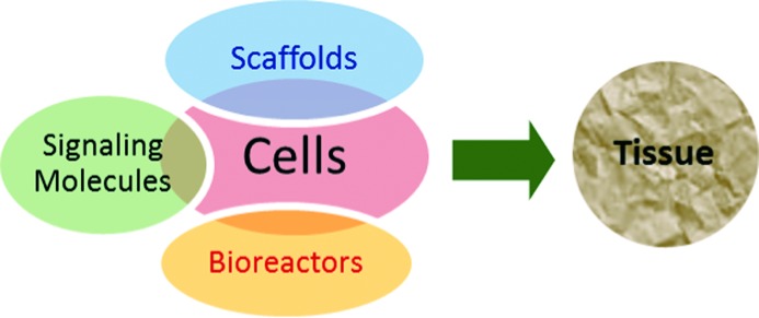
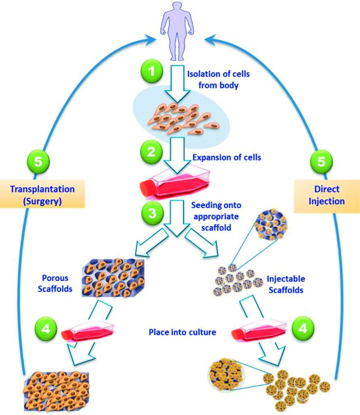
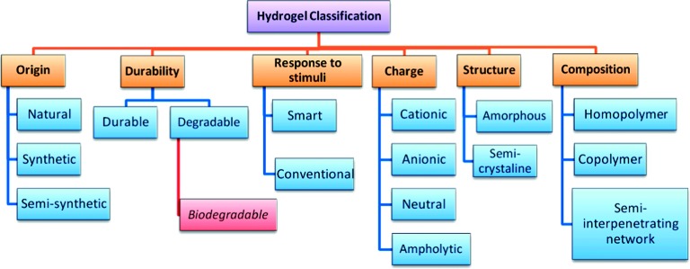
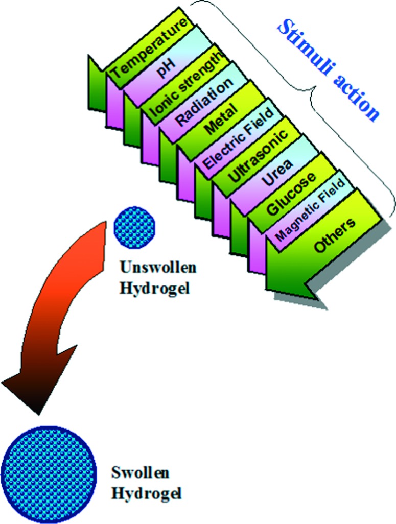
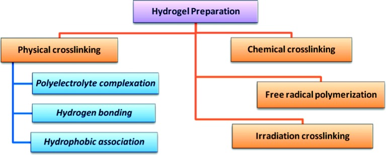
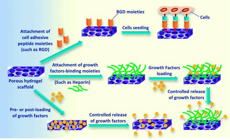
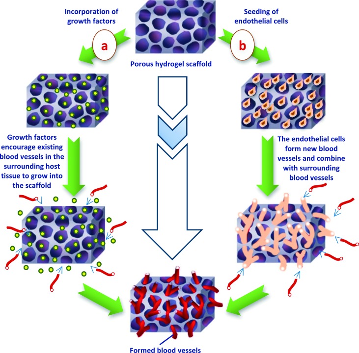
Designing of biologically active scaffolds with optimal characteristics is one of the key factors for successful tissue engineering. Recently, hydrogels have received a considerable interest as leading candidates for engineered tissue scaffolds due to their unique compositional and structural similarities to the natural extracellular matrix, in addition to their desirable framework for cellular proliferation and survival. More recently, the ability to control the shape, porosity, surface morphology, and size of hydrogel scaffolds has created new opportunities to overcome various challenges in tissue engineering such as vascularization, tissue architecture and simultaneous seeding of multiple cells. This review provides an overview of the different types of hydrogels, the approaches that can be used to fabricate hydrogel matrices with specific features and the recent applications of hydrogels in tissue engineering. Special attention was given to the various design considerations for an efficient hydrogel scaffold in tissue engineering. Also, the challenges associated with the use of hydrogel scaffolds were described.

Keywords: bioadhesion; biocompatibility, tissue engineering; biodegradability; hydrogels; scaffolds.


Figures

Figure 1.
Figure 1.
A schematic illustration of the four key components of tissue engineering.
Figure 2.
Figure 2.
Schematic illustration of the most common tissue engineering approaches. Tissue-specific cells are isolated from a small biopsy from the patient, expanded in vitro, seeded into a well-designed scaffold and transplanted into the patient either through injection, or via implantation at the desired site using surgery.
Figure 3.
Figure 3.
Schematic diagram showing the most common classes of hydrogels.
Figure 4.
Figure 4.
Stimuli-responsive swelling of a smart hydrogel.
Figure 5.
Figure 5.
Schematic diagram showing the most common methods of preparation of hydrogels.
Figure 6.
Figure 6.
Some approaches for selective enhancement of surface characteristics of hydrogel scaffolds toward increasing surface-cells attachment and controlled release of regulatory growth factors.
Figure 7.
Figure 7.
Schematic illustration of blood vessels formation encouraged by either (a) incorporating of regulatory growth factors or (b) via seeding of endothelial cells into the porous hydrogel scaffold.
Figure 8.
Figure 8.
Schematic illustration showing the basic structure of collagen hydrogel fibers. Images were adapted with modification from Buehler.
Figure 9.
Figure 9.
Schematic illustration of the self-assembled peptide-amphiphiles (SAPs) functionalized with cell adhesion ligand (RGD) into fibrous crosslinked hydrogel scaffold for bone tissue engineering applications. Images were adapted with modification from Hartgerink et al.
Figure 10.
Figure 10.
Schematic illustration of emulsification technique for fabrication of hydrogel particles scaffolds for tissue engineering applications.
Figure 11.
Figure 11.
Schematic illustration of gas foaming-leaching technique for fabrication of porous hydrogel scaffolds for tissue engineering applications.
Figure 12.
Figure 12.
Schematic illustration of photolithography technique for fabrication of hydrogel scaffolds for tissue engineering applications.
Figure 13.
Figure 13.
Schematic illustration of the basic electrospinning setup.
Figure 14.
Figure 14.
Schematic illustration of microfluidic technique.
Figure 15.
Figure 15.
(a) Organ/tissue printing using fiber deposition. Illustration was adapted with modification from , (b) macroscopic view of the dual graft (heterogeneous tissue formation in a printed construct implanted subcutaneously in mice) at 6 weeks; dashed line represents the transition zone between (left) printed MSCs in Matrigel and (right) EPCs in Matrigel/hematoxylin and eosin staining, scale bar = 200 mm. Image was adapted from .

References

    1. Langer R, Tirrell DA. Designing materials for biology and medicine. Nature. 2004;428:487–492. - PubMed
    1. Lee KY, Mooney DJ. Hydrogels for tissue engineering. Chem Rev. 2001;101(7):1869–1879. - PubMed
    1. Kyung JH, Yeon KS, Jeong KS, Moo LY. pH / temperature-responsive semi-IPN hydrogels composed of alginate and poly(N-isopropylacrylamide) J Appl Polym Sci. 2002;83:128–136.
    1. Wichterle O, Lim D. Hydrophilic gels for biological use. Nature. 1960;185:117–129.
    1. Hoffman AS. Hydrogels for biomedical applications. Ann N Y Acad Sci. 2001;944:62–73. - PubMed