

Carbon dioxide separation from flue gases: a technological review emphasizing reduction in greenhouse gas emissions
- PMID: 24696663
- PMCID: PMC3947793
- DOI: 10.1155/2014/828131
Carbon dioxide separation from flue gases: a technological review emphasizing reduction in greenhouse gas emissions
Abstract
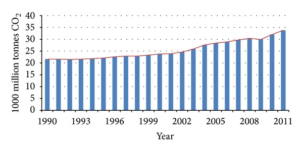
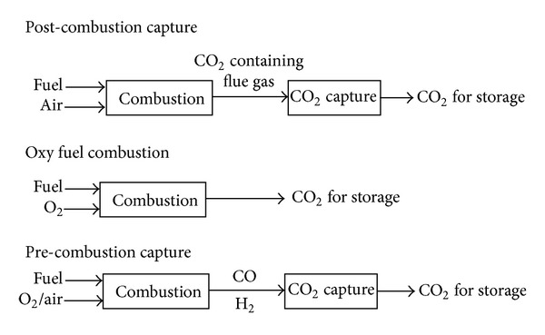
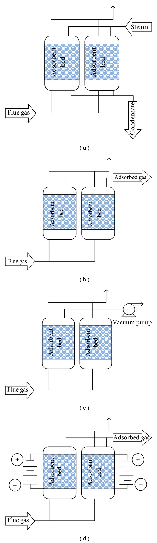
Increasing concentrations of greenhouse gases (GHGs) such as CO2 in the atmosphere is a global warming. Human activities are a major cause of increased CO2 concentration in atmosphere, as in recent decade, two-third of greenhouse effect was caused by human activities. Carbon capture and storage (CCS) is a major strategy that can be used to reduce GHGs emission. There are three methods for CCS: pre-combustion capture, oxy-fuel process, and post-combustion capture. Among them, post-combustion capture is the most important one because it offers flexibility and it can be easily added to the operational units. Various technologies are used for CO2 capture, some of them include: absorption, adsorption, cryogenic distillation, and membrane separation. In this paper, various technologies for post-combustion are compared and the best condition for using each technology is identified.
Figures


References
-
- Solomon SQ, D SQ, Manning M, et al. Book reviews. South African Geographical Journal. 2009;91:103–104.
-
- McMillan CA, Keoleian GA, Spitzley DV. Greenhouse Gases. Ann Arbor, Mich, USA : University of Michigan; 2005.
-
- Blasing TJ. Recent Greenhouse Gas Concentrations. 32 edition. US Department of Energy; 2012.
-
- Chiao CH, Chen JL, Lan CR, Chen S, Hsu HW. Development of carbon dioxide capture and storage technology taiwan power company perspective. Sustainable Environment Research. 2011;21:1–8.
-
- Dantas TLP, Luna FMT, Silva IJ, et al. Carbon dioxide-nitrogen separation through pressure swing adsorption. Chemical Engineering Journal. 2011;172(2-3):698–704.
Publication types
MeSH terms
Substances
LinkOut - more resources
Full Text Sources
Other Literature Sources
