

Commissioning and initial stereotactic ablative radiotherapy experience with Vero
- PMID: 24710458
- PMCID: PMC5875460
- DOI: 10.1120/jacmp.v15i2.4685
Commissioning and initial stereotactic ablative radiotherapy experience with Vero
Abstract
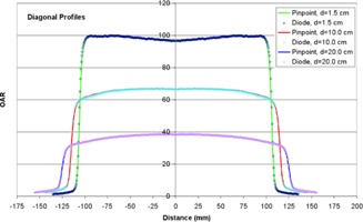
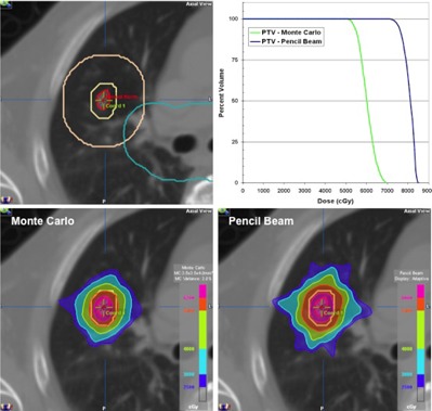
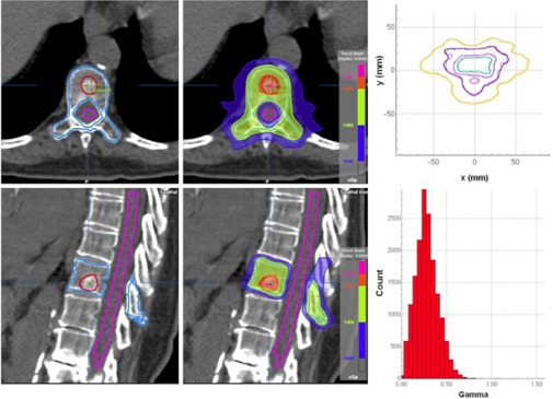
The purpose of this study is to describe the comprehensive commissioning process and initial clinical performance of the Vero linear accelerator, a new radiotherapy device recently installed at UT Southwestern Medical Center specifically developed for delivery of image-guided stereotactic ablative radiotherapy (SABR). The Vero system utilizes a ring gantry to integrate a beam delivery platform with image guidance systems. The ring is capable of rotating ± 60° about the vertical axis to facilitate noncoplanar beam arrangements ideal for SABR delivery. The beam delivery platform consists of a 6 MV C-band linac with a 60 leaf MLC projecting a maximum field size of 15 × 15 cm² at isocenter. The Vero planning and delivery systems support a range of treatment techniques, including fixed beam conformal, dynamic conformal arcs, fixed gantry IMRT in either SMLC (step-and-shoot) or DMLC (dynamic) delivery, and hybrid arcs, which combines dynamic conformal arcs and fixed beam IMRT delivery. The accelerator and treatment head are mounted on a gimbal mechanism that allows the linac and MLC to pivot in two dimensions for tumor tracking. Two orthogonal kV imaging subsystems built into the ring facilitate both stereoscopic and volumetric (CBCT) image guidance. The system is also equipped with an always-active electronic portal imaging device (EPID). We present our commissioning process and initial clinical experience focusing on SABR applications with the Vero, including: (1) beam data acquisition; (2) dosimetric commissioning of the treatment planning system, including evaluation of a Monte Carlo algorithm in a specially-designed anthropomorphic thorax phantom; (3) validation using the Radiological Physics Center thorax, head and neck (IMRT), and spine credentialing phantoms; (4) end-to-end evaluation of IGRT localization accuracy; (5) ongoing system performance, including isocenter stability; and (6) clinical SABR applications.
Figures


References
-
- Baumann P, Nyman J, Hoyer M, et al. Outcome in a prospective phase II trial of medically inoperable stage I non‐small‐cell lung cancer patients treated with stereotactic body radiotherapy. J Clin Oncol. 2009;27(20):3290–96. - PubMed
-
- Fakiris AJ, McGarry RC, Yiannoutsos CT, et al. Stereotactic body radiation therapy for early‐stage non‐small‐cell lung carcinoma: four‐year results of a prospective phase II study. Int J Radiat Oncol Biol Phys. 2009;75(3):677–82. - PubMed
-
- Onishi H, Shirato H, Nagata Y, et al. Stereotactic body radiotherapy (SBRT) for operable stage I non‐small‐cell lung cancer: can SBRT be comparable to surgery? Int J Radiat Oncol Biol Phys. 2011;81(5):1352–58. - PubMed
-
- Rusthoven KE, Kavanagh BD, Burri SH, et al. Multi‐institutional phase I/II trial of stereotactic body radiation therapy for lung metastases. J Clin Oncol. 2009;27(10):1579–84. - PubMed
MeSH terms
LinkOut - more resources
Full Text Sources
Other Literature Sources
