Review
. 2014 Jan;14(1):15-56.
doi: 10.1166/jnn.2014.9127.

Scaffold design for bone regeneration

Review

Scaffold design for bone regeneration

Liliana Polo-Corrales et al. J Nanosci Nanotechnol. 2014 Jan.

Abstract

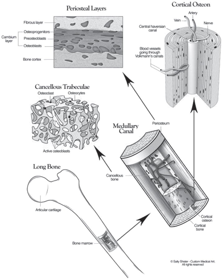
The use of bone grafts is the standard to treat skeletal fractures, or to replace and regenerate lost bone, as demonstrated by the large number of bone graft procedures performed worldwide. The most common of these is the autograft, however, its use can lead to complications such as pain, infection, scarring, blood loss, and donor-site morbidity. The alternative is allografts, but they lack the osteoactive capacity of autografts and carry the risk of carrying infectious agents or immune rejection. Other approaches, such as the bone graft substitutes, have focused on improving the efficacy of bone grafts or other scaffolds by incorporating bone progenitor cells and growth factors to stimulate cells. An ideal bone graft or scaffold should be made of biomaterials that imitate the structure and properties of natural bone ECM, include osteoprogenitor cells and provide all the necessary environmental cues found in natural bone. However, creating living tissue constructs that are structurally, functionally and mechanically comparable to the natural bone has been a challenge so far. This focus of this review is on the evolution of these scaffolds as bone graft substitutes in the process of recreating the bone tissue microenvironment, including biochemical and biophysical cues.


Figures

Figure 1
Figure 1
The three-dimensional structure of bone, which includes the cortical and a cancellous/trabecular component. Reprinted with permission from [12], D. Buck II and G. Dumanian, Plast Reconstr Surg. 129, 1314 (2012). © 2012, American Society of Plastic Surgeon.
Figure 2
Figure 2
Illustration of cellular metabolism-scaffold degradation model describing bone remodeling with fluxes representing expected pathways leading to the formation of new bone. (a) Model for rapidly degrading scaffold, and (b) model for slow degrading scaffolds. Solid arrows: metabolic flux. Dashed arrows: signal transduction. Colors: red and inhibition; green and activation. Reprinted with permission from [77], S.-H. Park, et al., Biomaterials 31, 6162 (2010). © 2010, Elsevier.
Figure 3
Figure 3
Schematic representations of the three protein delivery strategies: Collagen sponge-rhMBP-2, Alginate-BMP-2 and Alginate-rhBMP-2. Reprinted with permission from [86], Y. M. Kolambkar, et al., Bone 49, 485 (2011). © 2011, Elsevier.
Figure 4
Figure 4
SEM images of silicate 13–93 bioactive glass scaffolds which were prepared by robo-casting: (a) plane of deposition (xy plane); (b) perpendicular to the deposition plane (z direction). Reprinted with permission from [144], X. Liu, et al., Acta Biomaterialia 9, 7025 (2013). © 2013, Elsevier.
Figure 5
Figure 5
Photograph showing the Implantation of Ceramic Scaffolds with BMP-2 in rabbit bone. Top, images of the surgical procedure. (A) control scaffolds, (B) BMP-2 adsorbed scaffolds. (1) Gross appearance of harvested samples, (2) Representative mCT slides, (3) Representative histological images (Massons tricrome stainings). Reprinted with permission from [155], A. Abarrategi, et al., PLoS ONE 7, 34117 (2012). © 2012, PloS ONE.
Figure 6
Figure 6
Images demonstrating the vascularization of cell-CHA constructs at 4 weeks post-implantation using MSC-coral hydroxyapatite scaffold. CT angiography (A), (B) and ultrasonic inspection (C), (D). X-ray before and after vascular corrosion cast (E), (F) and vascular corrosion cast (G). HE and Masson’s trichrome staining of cell-CHA constructs in undecalcification sections (H), (I); and HE staining in decalcification sections (J). Scale bars: 10 mm (F), (G), 50 mm (H)–(J). Reprinted with permission from [177], L. Cai, et al., Biomaterials 32, 8497 (2011). © 2011, Elsevier.
Figure 7
Figure 7
Illustration showing the Wound chamber model in the tibia of New Zealand White rabbits using Ti and TiO2 scaffolds. Two defects of diameter 3 mm were made in the rabbit tibia (A) and the TiO2 scaffold (black arrow) was placed through the cortical defect and into the bone marrow and the sham defect left empty (B). SEM images of the TiO2 scaffold prior to implantation (C). Titanium coins which were placed on top of the defect to simulate a peri-implant situation. Teflon caps were placed on top of the coins to prevent bone growth on the side and a titanium band was placed to prevent the discs falling out (D). After healing, the band was carefully cut, and the Teflon caps were removed (E). The peri-implant bone attached to the extracted titanium discs was analyzed with real-time RT-PCR. The wound fluid was collected from the wound site with filter papers to test for cytotoxicity (F). The bone tissue was further analyzed with micro-CT and histology. The black arrow shows that the TiO2 scaffold promoted a complete healing of the cortical defect. Reprinted with permission from [191], H. J. Haugen, et al., Acta Biomaterialia 9, 5390 (2013). © 2013, Elsevier.
Figure 8
Figure 8
Photograph showing the tibial segmental bone defect of 2 cm length stabilized with a limited contact locking compression plate (LCLCP, Synthes) and filled with a PDLLA-TCP-PCL (a) and mPCL-TCP scaffold (c). Prior to scaffold insertion, the periosteum (b), which is in close proximity to the neurovascular bundle, was entirely removed within the defect area (d). Reprinted with permission from [211], J. C. Reichert, et al., Int Orthop (SICOT) 35, 1229 (2011). © 2013, Springer.
Figure 9
Figure 9
Differentiation of the osteoprogenitor cells and the role of growth factors during the temporal progression. Adapted from [33], F. Hughes, et al., Periodontol 2000 41, 48 (2006). © 2006, Blackwell Munksgaard; From [279], Y. Luu, et al., Bonekey Osteovision 6, 132 (2009). © 2009, Nature Publishing Group.

Similar articles

Cited by

References

    1. Neighbour T. The Global Orthobiologics Market: Players, Products and Technologies Driving Change. Espicom Business Intelligence. 2008;2
    1. Brydone A, Meek D, Maclaine S. Proc Inst Mech Eng H. 2010;224:1329. - PubMed
    1. Albrektsson T, Johansson C. Eur Spine J. 2001;(Suppl 2):S96. - PMC - PubMed
    1. Myeroff C, Archdeacon M. J Bone Joint Surg Am. 2011;93:2227. - PubMed
    1. Oppenheim J, Segal D, Spitzer D. Neurosurgery. 2002;51:854. - PubMed

Publication types

Substances