Review
. 2014 Jan 8;26(1):85-123.
doi: 10.1002/adma.201303233.

25th anniversary article: Rational design and applications of hydrogels in regenerative medicine

Review

25th anniversary article: Rational design and applications of hydrogels in regenerative medicine

Nasim Annabi et al. Adv Mater. .

Abstract

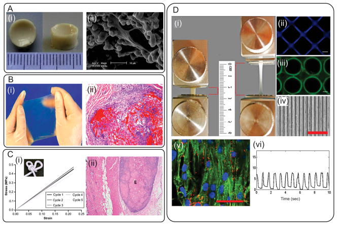
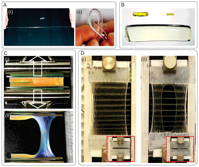
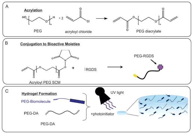
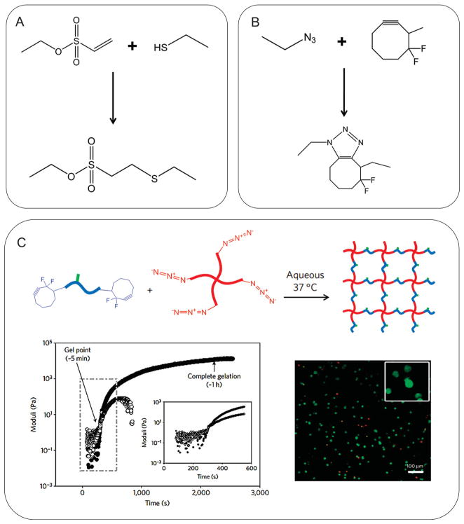
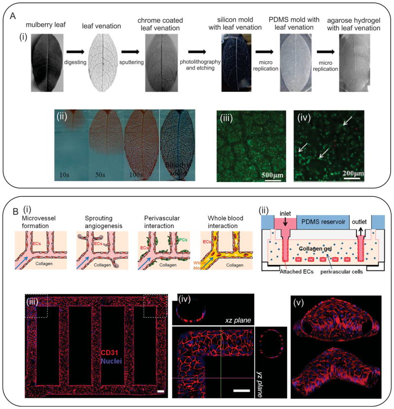
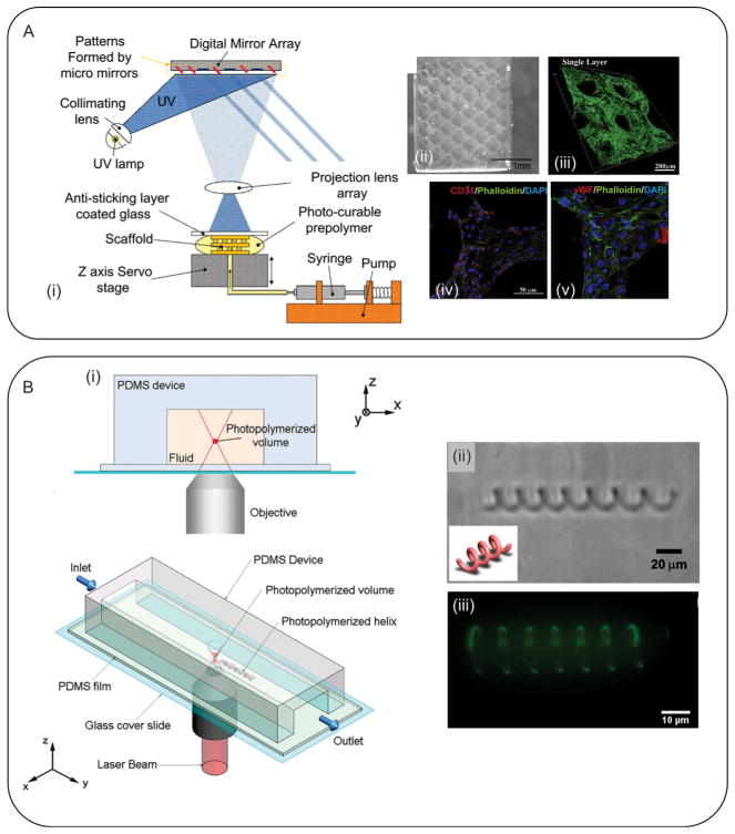
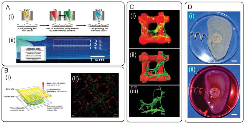
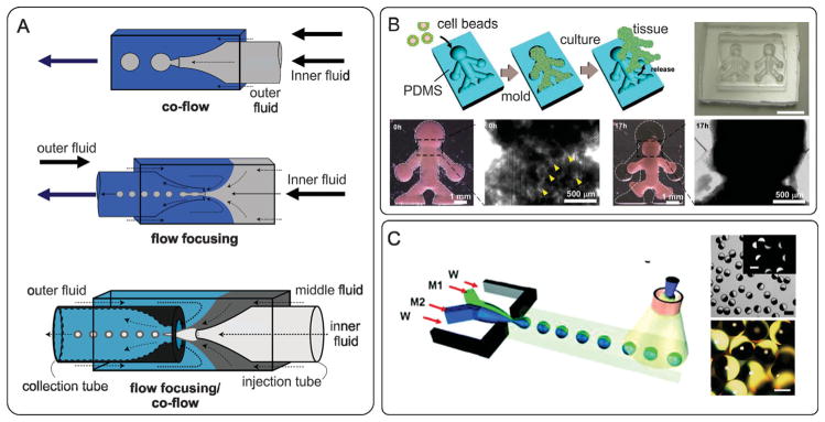
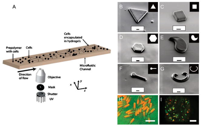
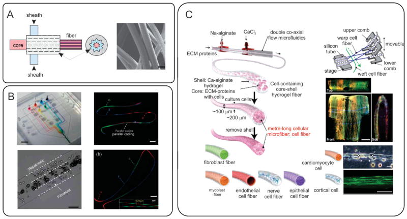
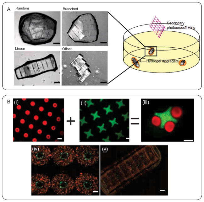
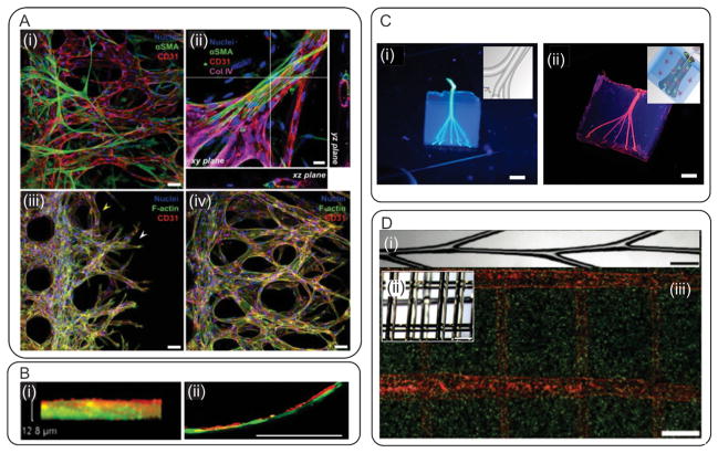
Hydrogels are hydrophilic polymer-based materials with high water content and physical characteristics that resemble the native extracellular matrix. Because of their remarkable properties, hydrogel systems are used for a wide range of biomedical applications, such as three-dimensional (3D) matrices for tissue engineering, drug-delivery vehicles, composite biomaterials, and as injectable fillers in minimally invasive surgeries. In addition, the rational design of hydrogels with controlled physical and biological properties can be used to modulate cellular functionality and tissue morphogenesis. Here, the development of advanced hydrogels with tunable physiochemical properties is highlighted, with particular emphasis on elastomeric, light-sensitive, composite, and shape-memory hydrogels. Emerging technologies developed over the past decade to control hydrogel architecture are also discussed and a number of potential applications and challenges in the utilization of hydrogels in regenerative medicine are reviewed. It is anticipated that the continued development of sophisticated hydrogels will result in clinical applications that will improve patient care and quality of life.


Figures

Figure 1
Figure 1
Examples of naturally-derived elastin-based hydrogels. A) GA crosslinked rTE/elastin hydrogels produced under high pressure CO2; i) structure of the hydrogel after swelling, ii) SEM image of dermal fibroblast cells penetrated and attached within the 3D structure of the gel. Reproduced with permission.[52] Copyright 2010, Elsevier B.V. B) BS3 crosslinked rTE gel; i) an image from an elastic hydrogel sheet, (ii) hematoxylin and eosin-stained sample explanted after 13 weeks of implantation (hydrogel is shown in bright red). Reproduced with permission.[57] Copyright 2004, Elsevier B.V. C) Physically crosslinked rTE gel; i) representative stress–strain curves over 5 cycles, the resulting gel could be tied in a knot, demonstrating its high flexibility, ii) a hematoxylin and eosin-stained explant showing the injection site (the elastic deposit is marked with an E). Reproduced with permission.[55] Copyright 2009, Elsevier B.V. D) Methacrylated rTE gel; i) image of an elastic MeTro gel before and after stretching, ii–iv) formation of patterns with various geometries on MeTro gel by using different microfabrication techniques, v) immunostaining of CM markers on MeTro gel on day 8 of culture, gel stained for sarcomeric α-actinin (green)/connexin-43 (red)/nuclei (blue) (scale bar = 50 μm), vi) beating behavior of CMs on micropatterned MeTro gel. Reproduced with permission[13] Copyright 2013, Elsevier B.V; Reproduced with permission.[56] Copyright 2013, John Wiley & Sons, Inc.
Figure 2
Figure 2
Examples of composite elastomers. A) N-isopropylacrylamide/clay nanocomposite hydrogel; i) with high level of elongation and ii) torsion. Reproduced with permission.[95] Copyright 2002, John Wiley & Sons, Inc. B) Volume change of a superabsorbent polyrotaxane gel swelled to 45 times the initial weight; before volume change, in dried state, and in swollen state (up to 400% of its dry weight). Reproduced with permission.[97] Copyright 2001, John Wiley & Sons, Inc. C) Crack resistance of a PDGI/PAAm gel; (i) hydrogel with an initial sharp crack along the longitudinal direction, (ii) the hydrogel was stretched perpendicular to the crack direction up to a strain of 3. Reproduced with permission.[99] Copyright 2011, American Chemical Society. D) Highly stretchable alginate/acrylamide gel; i) the gel was glued to two rigid clamps and stretched up to 21 times its initial length, ii) a notch was cut into the gel before stretching to 17 times its initial length. Reproduced with permission.[100] Copyright 2012, Nature Publishing Group.
Figure 3
Figure 3
Schematic for generation of photocrosslinkable hydrogels. A) Modification of PEG polymer with photocrosslinkable acrylate groups. B) Conjugation of biological molecules to photocrosslinkable PEG polymer precursor. C) Formation of hydrogel upon exposure to UV light. Reproduced with permission.[112] Copyright 2011, Wiley Periodical Inc.
Figure 4
Figure 4
Biocompatible click-based hydrogels. A) A Michael-type addition between thiol and vinyl sulfone. B) A “copper-free” click chemistry between azide and difluorinated cyclooctyne. Both reactions occurred under physiological conditions. C) Cell-encapsulating hydrogel was fabricated by copper-free click chemistry between 4-arm PEG-tetrazide and bis(difluorocyclooctyne)-polypeptide. Reproduced with permission.[166] Copyright 2009, Nature Publishing Group.
Figure 5
Figure 5
Nanocomposite hydrogels as bioactuators. A) A magnetic triggered composite film consisting of iron oxide MNPs and PNIPAm hydrogels. The magnetic-induced hyperthermia from the iron oxide MNPs caused shrinkage of PNIPAm hydrogel, inducing the release of cancer drugs. Reproduced with permission.[193] Copyright 2009, American Chemical Society. B) CNTs were embedded in GelMA hydrogel to engineer electrically conductive tissue engineering scaffold. CMs on CNT-GelMA composite hydrogels displayed enhanced electrophysiological functions (identified with the expression of various cardiac markers including sarcomeric α-actinin, connexin 43, and troponin I), compared to pure GelMA hydrogels. Reproduced with permission.[195] Copyright 2013, American Chemical Society.
Figure 6
Figure 6
Molecular mechanism of temperature-responsive SMHs. The left panels represent the TT related to the switching of conformational structure. The right panel represents the conformational change of the SMH from shape B to shape A upon cooling, and back from shape A to shape B upon application of heat. The covalent chemical bonds are represented by the red dots and the physical non-covalent bonds by the entangled lines. Reproduced with permission.[222] Copyright 2013, American Chemical Society.
Figure 7
Figure 7
Representative examples of SMHs. A) Formation of injectable SMHs: i) cryogelation process: 1) alginate is chemically modified to allow radical polymerization; 2) MA-alginate is added to a chemical initiator at −20 °C to allow ice crystal formation; 3) cryogelation takes place followed by thawing of ice crystals; and 4) conventional needle–syringe injection of preformed cryogels; ii) Photographs showing placement of a cryogel in a syringe (before injection) and hydrogel recovery (after injection); iii) MA-alginate gels with various sizes and shapes. Fluorescent square-shaped gels were syringe injected and showed complete geometric restoration after injection; iv) Cryogels prepared with different geometric shapes. Reproduced with permission.[235] Copyright 2012, National Academy of Sciences. B) Shape-memory behavior of highly stretchable hydrogels: i) The original length of the hydrogel is 26.3 mm; ii) The hydrogel heated in 65 °C water and stretched to 45.2 mm; iii) The shape of the hydrogel immediately after cooling to 10 °C; iv) After 24 h soaking in 10 °C water, the length of hydrogel decreased to 43.0 mm; v) After reheating hydrogel in 65 °C water without any external stress, the length recovered to 26.0 mm. Reproduced with permission.[239] Copyright 2009, American Chemical Society.
Figure 8
Figure 8
Photopatterning of hydrogel constructs. A) Fabrication of cell-laden PEGDA constructs for liver tissue engineering; i,ii) schematic of the additive photopatterning process, in which different cell-laden hydrogels were photocrosslinked sequentially using different photomasks to create a 3D construct, iii) Micrograph image of a typical fabricated cell-laden hydrogel construct. Reproduced with permission.[257] Copyright 2007, The Federation of American Societies for Experimental Biology. B) Typical structures fabricated by degrading the surface of hydrogels; the hydrogel surface under 100 μm (i) squares and (iii) spiral masks were partially degraded and swell to form positive features observed in (i) and (iv). Reproduced with permission.[266] Copyright 2010, American Chemical Society.
Figure 9
Figure 9
Micromolding of hydrogel constructs. A) Fabrication of a biomimetic microvascular network within agarose hydrogel using a soft lithography process; i) the soft tissue of a leaf was digested and its veins were sputtered with a chrome layer. The sputtered leaf was used as a photomask in soft lithography. The fabricated PDMS mold was used for fabrication of agarose hydrogel containing microvessels; ii) injection of dye within the fabricated agarose samples; iii) HepG2 cell-laden agarose with perfusable microchannels as a model for liver tissue engineering; iv) the HUVECs seeded within the microchannels formed capillaries. Reproduced with permission.[269] Copyright 2013, John Wiley & Sons, Inc. B) Pre-vascularized collagen hydrogel fabricated using micromolding; i) Schematics showing different scenarios that were studied including morphology and barrier function of endothelium, endothelial sprouting, perivascular association, and blood perfusion for fabrication; ii) schematic of the employed microfluidic system; (iii)–(v) confocal images from endothelialized microfluidic, showing the formation of circular vessels. Reproduced with permission.[270] Copyright 2012, National Academy of Sciences.
Figure 10
Figure 10
Fabrication of hydrogel constructs using rapid prototyping. A) SLA with digital mirror device for fabrication of GelMA constructs; i) Schematic representing SLA device with was controlled by a CAD software; (ii) a typical scaffold fabricated using the device; iii) the fabricated scaffold seeded with HUVECs-GFP; iv,v) staining showing the spreading of HUVECs on the surface of the fabricated scaffolds; Reproduced with permission.[281] Copyright 2012, Elsevier B.V. B) Two-photon continuous flow lithography; i) schematic of the employed the device; prepolymer was flown through the channel while a 2PP system was used for crosslinking of prepolymer. ii,iii) bright field and confocal images of a typical fabricated helix-shaped PEGDA. Reproduced with permission.[282] Copyright 2012, John Wiley & Sons, Inc.
Figure 11
Figure 11
Bioprinting of hydrogels for tissue engineering. A) Inkjet bioprinting approach: i) schematic illustration of a layer-by-layer printing of single cells and proteins; ii) inkjet bioprinted 3D human-tissue chips. Reproduced with permission.[298] Copyright 2011, John Wiley and Sons. B) Laser bioprinting approach: i) Schematic illustration of a laser forward transfer technique (LIFT); ii) A bioprinted cardiac-patch micropatterned with human MSC (PKH26-green) and HUVECs (PECAM-1-red). Reproduced with permission.[87] Copyright 2011, Elsevier. C) Direct-write bioprinting: i) Confocal image of microperiodical pHEMA scaffold fabricated via direct-write bioprinting method; ii) Software reconstruction of bioprinted scaffolds (red) and primary rat hippocampal neurons (green); iii) Software reconstruction of cells alone, demonstrating cell processes guided by scaffold architecture. Reproduced with permission.[300] Copyright 2011, John Wiley and Sons. D) Example of bioprinting integrated with bioelectronics for engineering of whole body parts: i) a bioprinted alginate hydrogel scaffold integrated with an electrically conductive silver nanoparticle (AgNP)-infused inductive coil antenna; ii) Scaffolds seeded with chondrocytes forming an ear-like construct with functional hearing capabilities. Reproduced with permission.[301] Copyright 2011, American Chemical Society.
Figure 12
Figure 12
Emulsion-based systems for creating microengineered hydrogels (microgels) and their applications in tissue engineering. A) Microfluidic methods for creating microgels by using co-flow, flow focusing, and their combination. Reproduced with permission.[342] Copyright 2007, Cambridge University Press. B) Application of cell-loaded microgels for rapid fabrication of tissue constructs. Collagen microgels were fabricated using the flow focusing method and subsequently were seeded with mammalian cells. NIH 3T3-seeded hydrogel beads were tipped into a doll-shaped PDMS mold to a large-scale 3D tissue construct. Reproduced with permission.[343] Copyright 2011, John Wiley and Sons. C) Fabrication of Janus-like particles using a microfluidic flow focusing system. The chemical properties of the particles are adjusted by tuning the flow rate of the two streams (M1 and M2) that merge at the focusing point. Reproduced with permission.[332,344] Copyright 2005, 2008, John Wiley and Sons.
Figure 13
Figure 13
Flow lithography for in situ fabrication of cell-laden microgels with complex morphological and chemical properties. (A) Schematic of the flow lithography. Reproduced with permission.[349] Copyright 2008, The Royal Society of Chemistry. B–G) Highly complex microgels fabricated using the flow lithography technique. H) Janus-like hydrogels with spatially controlled chemical properties. Reproduced with permission.[348] Copyright 2006, Nature Publishing Group. I) Cells encapsulated in a microgel, green cells are live and red cells are dead. Reproduced with permission.[349] Copyright 2008, The Royal Society of Chemistry.
Figure 14
Figure 14
Fiber-based methods for creating functional tissue constructs. A) Creating grooved fibers by using a microfluidic grooved spinneret. Reproduced with permission.[334] Copyright 2011, Nature Publishing Group. B) Microfluidic devices that enables creating fibers with spatially controlled topography and chemical composition. Reproduced with permission.[334] Copyright 2011, Nature Publishing Group. C) Microfluidic fabrication of functional fibers. A core-shell fiber is formed in a coaxial flow microfluidic device. Cells are encapsulated in the core made from ECM proteins and the shell is made from Ca-alginate. Functional fibers can be assembled to form complex tissue constructs using a miniaturized weaving loom. Reproduced with permission.[357] Copyright 2013, Nature Publishing Group.
Figure 15
Figure 15
Assembly of microgels. A) Schematic diagram of the assembly process; cell-laden modules were immersed inside a hydrophobic oil where they self assembled to minimize the surface energy; Reproduced with permission.[388] Copyright 2008, National Academy of Sciences. B) Fabricated modules and their assembly; i–iii) lock-and-key constructs loaded with FITC-dextran and Nile red; iv,v) rings containing concentric layers of HUVEC- and SMC-laden hydrogel; these rings were assembled to form a microvessel. Reproduced with permission.[384] Copyright 2011, John Wiley & Sons, Inc.
Figure 16
Figure 16
Vascularization in tissue engineered constructs. A) Microvascular network fabricated in a microfluidic chip. i) Endothelial cells (CD31-red) interacting with pericytes (alpha-SMA-green) to form perfusable microvascular systems. ii) At higher magnification, the presence of a patent lumen and deposition of ECM (Col IV, pink) are visible from the confocal sections in XZ and YZ. iii–iv) A sprouting assay demonstrates the high-proliferation of mature tubules given the presence of U87MG cancer cells after 2 and 4 days of culture. Reproduced with permission.[414] Copyright 2013, The Royal Society of Chemistry. B) Layer-by-layer assembly of cellular multilayers i) fibronectin-gelatin nanofilms in a co-culture of human umbilical artery smooth-muscle cells and HUVECs. ii) This technique was utilized to form biomimetic multilayered blood vessels with improved selective permeability. Reproduced with permission.[405] Copyright 2007, John Wiley and Sons. C) Photographs of microvascular beds in GelMA hydrogels. i) Bioprinted 500 μm agarose templates surrounded by a GelMA hydrogel replicating 3D branched microvascular structures. ii) After removing the agarose, a patent microvascular network is shown after perfusion with a fluorescent dye (unpublished results). D) Sacrificial glass-carbohydrate as a template for microvascular network fabrication. i) A glass-carbohydrate template bioprinted with a branching architecture to form microvascular systems. ii) 3D lattice architectures of the bioprinted template allowed for the formation of thick cell-laden hydrogel constructs with high cell viability. iii) After sacrificing the glass-carbohydrate, a patent network remained and HUVECs (red) were perfused inside the lumen of a pericyte-laden (10T1/2, green) hydrogel. Reproduced with permission.[271] Copyright 2013, Nature Publishing Group.
Figure 17
Figure 17
Transdermal injection of photocrosslinkable PEG/HA hydrogels. A) The composite blend was injected into the dermis, B) the uncrosslinked mixture was massaged into the desirable shape under the skin, C) the material was then crosslinked by using an array of LEDs emitting light, which penetrated up to 4 mm of tissue depth. Reproduced with permission.[424] Copyright 2011, Advancing Science, Serving Society.

References

    1. Peppas NA, Hilt JZ, Khademhosseini A, Langer R. Adv Mater. 2006;18:1345.
    1. Slaughter BV, Khurshid SS, Fisher OZ, Khademhosseini A, Peppas NA. Adv Mater. 2009;21:3307. - PMC - PubMed
    1. Annabi N, Nichol JW, Zhong X, Ji C, Koshy S, Khademhosseini A, Dehghani F. Tissue Eng, Part B. 2010;16:371. - PMC - PubMed
    1. Khademhosseini A, Langer R, Borenstein J, Vacanti JP. Proc Natl Acad Sci USA. 2006;103:2480. - PMC - PubMed
    1. Seliktar D. Science. 2012;336:1124. - PubMed

Publication types