

Kinematics of visually-guided eye movements
- PMID: 24751602
- PMCID: PMC3994052
- DOI: 10.1371/journal.pone.0095234
Kinematics of visually-guided eye movements
Abstract
One of the hallmarks of an eye movement that follows Listing's law is the half-angle rule that says that the angular velocity of the eye tilts by half the angle of eccentricity of the line of sight relative to primary eye position. Since all visually-guided eye movements in the regime of far viewing follow Listing's law (with the head still and upright), the question about its origin is of considerable importance. Here, we provide theoretical and experimental evidence that Listing's law results from a unique motor strategy that allows minimizing ocular torsion while smoothly tracking objects of interest along any path in visual space. The strategy consists in compounding conventional ocular rotations in meridian planes, that is in horizontal, vertical and oblique directions (which are all torsion-free) with small linear displacements of the eye in the frontal plane. Such compound rotation-displacements of the eye can explain the kinematic paradox that the fixation point may rotate in one plane while the eye rotates in other planes. Its unique signature is the half-angle law in the position domain, which means that the rotation plane of the eye tilts by half-the angle of gaze eccentricity. We show that this law does not readily generalize to the velocity domain of visually-guided eye movements because the angular eye velocity is the sum of two terms, one associated with rotations in meridian planes and one associated with displacements of the eye in the frontal plane. While the first term does not depend on eye position the second term does depend on eye position. We show that compounded rotation - displacements perfectly predict the average smooth kinematics of the eye during steady- state pursuit in both the position and velocity domain.
Conflict of interest statement
Figures
 , a second rotation in the frontal plane LNR through ξ subtending the arc NN′, abbreviated by
  , a third rotation in the meridian plane OBN′ through η′ subtending the arc OB, abbreviated by
  , and finally a forth rotation in the eye′s coronal plane through –ξ, abbreviated
  to eliminate the acquired torsion. Denoting by
  and
and  the unit gaze vectors parallel to
  and
and  , respectively, we have altogether
  . For small angles ξ,
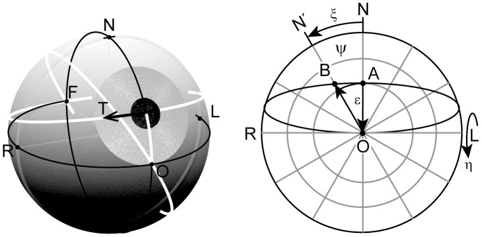
  approximates a smooth Listing-motion from A to B along the direction-circle arc. Left panel, sketch of the eye: O, primary position; F, occipital position, antipodal to O; N, R, L, defining north, right and left directions in the eye’s coronal plane; direction- circle (white), circle passing through center of pupil and F. Right panel, front view onto the eye with spherical coordinate grid: ψ, meridian angle; ξ, rotation angle; ε, eccentricity relative to O along circles ψ = constant; η, rotation angle in planes ψ = constant.
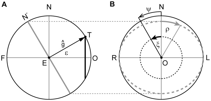
 gaze direction straight ahead and F, occipital fixation point. The unit gaze vector
  represents the direction of the line of sight, parallel to
  , to the fixation point T. Fixation points are parameterized by the spherical polar coordinates ψ, ε. (B) Front view on the spherical field of fixations, displaying ξ, angle of ocular rotation in the frontal plane LNR;
  , angle of ocular rotation in the eye’s coronal plane LN′R. For further details see text.
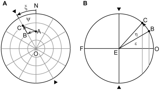
 the fixation point A (gaze parallel to
  ) moves through a small angle ξ approximately along the arc AB from A to B. Similarly, under the action of the meridian operator
  the new fixation point B (gaze parallel to
  ) moves through a small angle η along the arc BC from B to C. If both the Donders-Listing and meridian operator act simultaneously the fixation point moves along the arc AC from A to C. Format similar as in Figures 1 and 2.
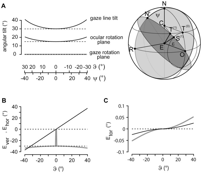
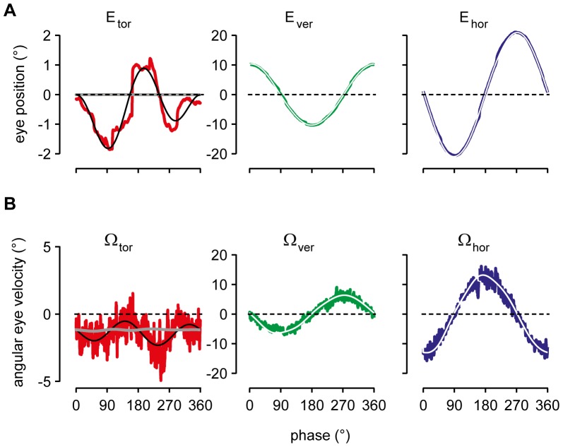
 (i = 1, 2 …N) plotted against meridian angle ψ or azimuth angle
  . Middle black curve: Reconstructed eccentricity of ocular rotation plane plotted against meridian ψ or azimuth
  . Note increasing tilt of these two curves with increasing absolute azimuth
  . Bottom thick gray curve: Angular tilt of rotation plane of gaze line, remaining perfectly invariant during tracking motion. B: Simulated vertical (gray line) and horizontal component (black line) of 3D eye position plotted against azimuth (
 ); onset of tracking to the left and right at straight ahead. C: Simulated torsional component (black line: 10 Hz sampling rate as in A and B; gray line: 5 Hz sampling rate). Inset: azimuth
  (not displayed), angle subtended by small circle arc from
  to
to  ; Listing’s plane, plane through E, N and R; line segment
  , primary gaze direction; T(0), initial target position; S(1), intermediate position, virtually traversed while tracking the target from T(0) to T(1) (for more details see Results).
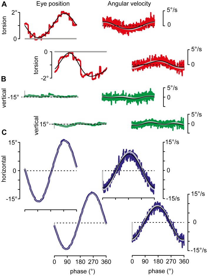
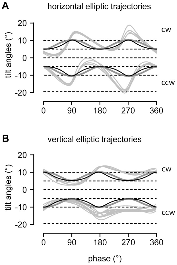
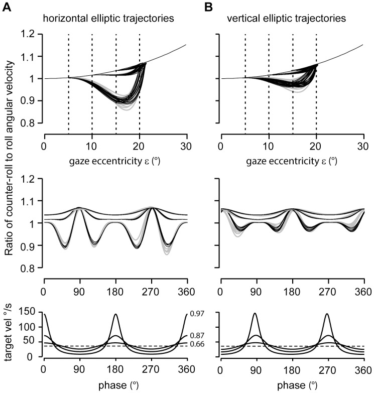
 , extending from 1 at ε = 0° to 1.15 at ε = 30°. Middle panels: Counter-roll to roll ratios as above plotted against tracking phase. Note increasing depth of modulation with increasing elliptic eccentricity, particularly during horizontal elliptic tracking. Abscissa: phase 0°, up gaze; phase +90°, rightward gaze position. Bottom panels: Torsional target velocity along the three elliptic trajectories with eccentricities 0.97, 0.87, and 0.66 plotted against phase angle. Dashed line indicates average torsional angular velocity across the three trajectories (36°/s).
References
-
- Gibson JJ (1950) The perception of the visual world. Boston: Houghton Mifflin. 235 p.
-
- Helmholtz H (1867) Handbuch der Physiologischen Optik, Leipzig: Leopold Voss. 874 p.
-
- Donders FC (1848) Beitrag zur Lehre von den Bewegungen des menschlichen Auges. Holländische Beiträge zu den anatomischen und physiologischen Wissenschaften 1: 105–145.
-
- Tweed D, Vilis T (1990) Geometric relations of eye position and velocity vectors during saccades. Vision Res 30: 111–127. - PubMed
-
- Henn V (1997) History of three-dimensional eye movement research. In: Fetter M, Haslwanter T, Misslisch H, Tweed D, editors. Three-Dimensional Kinematics of Eye, Head and Limb Movements. Amsterdam: Harwood Academic Publishers. 3–14.
Publication types
MeSH terms
LinkOut - more resources
Full Text Sources
Other Literature Sources
