. 2014 Apr 23;34(17):6065-77.
doi: 10.1523/JNEUROSCI.4198-13.2014.

The generation of antiphase oscillations and synchrony by a rebound-based vertebrate central pattern generator

Affiliations

The generation of antiphase oscillations and synchrony by a rebound-based vertebrate central pattern generator

Wen-Chang Li et al. J Neurosci. .

Abstract

Many neural circuits are capable of generating multiple stereotyped outputs after different sensory inputs or neuromodulation. We have previously identified the central pattern generator (CPG) for Xenopus tadpole swimming that involves antiphase oscillations of activity between the left and right sides. Here we analyze the cellular basis for spontaneous left-right motor synchrony characterized by simultaneous bursting on both sides at twice the swimming frequency. Spontaneous synchrony bouts are rare in most tadpoles, and they instantly emerge from and switch back to swimming, most frequently within the first second after skin stimulation. Analyses show that only neurons that are active during swimming fire action potentials in synchrony, suggesting both output patterns derive from the same neural circuit. The firing of excitatory descending interneurons (dINs) leads that of other types of neurons in synchrony as it does in swimming. During synchrony, the time window between phasic excitation and inhibition is 7.9 ± 1 ms, shorter than that in swimming (41 ± 2.3 ms). The occasional, extra midcycle firing of dINs during swimming may initiate synchrony, and mismatches of timing in the left and right activity can switch synchrony back to swimming. Computer modeling supports these findings by showing that the same neural network, in which reciprocal inhibition mediates rebound firing, can generate both swimming and synchrony without circuit reconfiguration. Modeling also shows that lengthening the time window between phasic excitation and inhibition by increasing dIN synaptic/conduction delay can improve the stability of synchrony.

Keywords: central pattern generator; locomotion; oscillations; spinal cord; swimming; synchrony.


Figures

Figure 1.
Figure 1.
Tadpole spinal/hindbrain neurons and their synaptic connections. Rohon-Beard (RB) neurons are the mechanosensory neurons that sense touch in the skin. Sensory interneurons include dlcs, dlas, and ecINs. Swimming CPG neurons include dINs, cINs, aINs, and MNs. dINrs and ecINs are only active during struggling (Li et al., 2007). The triangle synapse is excitatory, and the filled circle synapse is inhibitory. Synapses on the box means that all neurons inside the box receive inputs. Only sensory pathways on the left are shown to simplify the illustration.
Figure 2.
Figure 2.
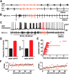
Left–right motor synchrony in tadpoles and its basic features. A, A synchrony bout with left and right m.n. activity recorded simultaneously (both fifth/sixth muscle cleft). B, Synchrony after single skin stimulation (arrow). C, Synchrony after repetitive skin stimulation (gray bar) with a simultaneous motoneuron recording. D, Synchrony rhythm frequency and phase (red bars) compared with that of adjacent swimming (black bars). E, Starting time (beginning of red lines) and duration (length of lines) for 37 synchrony bouts after single skin stimulation in 13 tadpoles. F, Cycle-by-cycle phase measurements of two synchrony bouts. Left, Example lacking a phase drift (linear regression coefficient is 0.0004 per cycle; R2 = 0.006; p = 0.62). Right, Example with the clearest phase drift with the progression of synchrony (coefficient is 0.0036 per cycle; R2 = 0.41; p < 0.001). Solid lines are for linear regression. Synchrony bouts are red traces, and swimming activity is black in this and other figures.
Figure 3.
Figure 3.
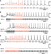
Activity of spinal and hindbrain neurons during synchrony and swimming. Four types of CPG neurons (A, aIN; B, motoneuron; C, cIN; D, dIN) and a dlc (E) are illustrated. Gray bars indicate periods of repetitive skin stimulation (30 Hz). Note the abrupt doubling and halving of rhythm frequencies when synchrony starts and ends. Synchrony cycles with failure in spiking are marked with filled triangles.
Figure 4.
Figure 4.
Analyses of dIN activity during swimming and synchrony. A, A synchrony bout shortly after swimming is started by single-pulse skin stimulation (arrow) in a paired recording. B, Overlapped traces of swimming and synchrony cycles from A at a smaller time scale to show the time of neuronal firing. Traces are lined up to the rising phase of the first dIN spike. Note dIN spikes reliably precede cIN spikes in both swimming and synchrony cycles. Latency is the time difference when spikes cross 0 mV. C, Spiking latencies between dINs and other CPG neurons in paired recordings are not different during swimming and synchrony. D, Rebound time measured from the start of IPSPs to the time when dIN spikes cross 0 mV. E, Rebound time for swimming and synchrony is not different.
Figure 5.
Figure 5.
Synaptic currents and potentials in dINs during synchrony and swimming. A, Rhythmic on-cycle EPSCs (membrane potential clamped at approximately −55mV). The right bar chart summarizes averaged measurements in 11 neurons. B, Rhythmic IPSCs (membrane potential clamped at ∼0 mV). The bar chart is for averaged midcycle IPSC measurements in eight neurons. Arrows point at early-cycle IPSCs from aINs. C, Delay from on-cycle EPSC peak (triangles) to midcycle IPSC peak (filled triangles). The right bar chart shows the delay is much shortened during synchrony compared with that in swimming. Significance values as follows: *p < 0.05; **p < 0.01; ***p < 0.001. D, dIN spiking is inhibited by IPSPs on some cycles during a synchrony bout (asterisks). dINs are recorded in voltage-clamp mode (A–C) and in current-clamp mode (D). Synch, Synchrony.
Figure 6.
Figure 6.
Extra midcycle dIN firing may initiate synchrony. A, Midcycle dIN firing (filled triangles) before and after a synchrony bout. B, Some examples of midcycle dIN firing showing the relative timing of the firing and cIN inhibition (triangles). Note some spikes are narrowed by inhibition (*). Lack of midcycle burst in the overlapped left m.n. recording implies the absence of synchrony in the circuit. The illustrated cycles are normalized based on dIN spiking. C, Depolarizing DC injection (gray bar) into a dIN during swimming results in reliable midcycle firing (filled triangles). Note the midcycle spikes do not divide the swimming cycle equally. D, DC injections into a motoneuron result in multiple firing (*) in many cycles and some midcycle firing (filled triangles). E, Summary of 12 dINs' (filled bar) and 16 non-dINs' (unfilled) firing after DC injections during swimming. Significance values as follows: **p < 0.01; ***p < 0.001. F, Midcycle firing of a right-side dIN coincides with synchrony in the left m.n. recording during the DC injection period (filled triangle marks one “swimming-like” cycle; compare with filled triangles in C). C and F are from the same dIN.
Figure 7.
Figure 7.
The effects of weakening inhibition on synchrony and dIN firing. A, Synchrony bouts in control, when 0.5 μm strychnine was applied and during wash. The arrow indicated time of skin stimulation. B, Midcycle dIN firing (arrowheads) induced by DC injection (gray bar) during swimming (control) and its suppression by 0.5 μm strychnine.
Figure 8.
Figure 8.
Synchrony initiation and features in a computer model. A, Swimming is converted to self-sustaining synchrony by injecting brief step currents (150 pA, 5 ms) into all dINs on the right once (step). Only one dIN (thick line) and one motoneuron (hairline) traces are shown for simplicity. B, Comparing CPG neuron firing reliabilities during swimming (black) and synchrony (red). C, Comparing synaptic conductance in dINs during swimming (black) and synchrony (red). dIN AMPAR conductance is comparable with on-cycle EPSCs during real swimming. cIN inhibition compares midcycle glycinergic conductance during swimming with the combined inhibitory conductance during synchrony (compare Fig. 5, A and B). ***p < 0.001; **p < 0.01. More details on modeling are in the Results.
Figure 9.
Figure 9.
Testing synchrony stability in modeling. A, Synchrony evoked by step current injections into dINs on the right is stopped and converted back to swimming by injecting brief step currents once into all dINs on the left (step), which advances neuronal activity by ∼2.27 ms. B, Increasing dIN–cIN synaptic/conduction delay from 1 to 2 ms converts synchrony to a stable output (>100 cycles, continuous at the end of the 3 s simulation). C, Percentage of trials with stable, evoked synchrony as in B increases with longer dIN-cIN transmission/conduction delays. D, CPG firing reliabilities during synchrony increase with dIN–cIN delays (p < 0.001 in each neuron type, one-way ANOVA).
Figure 10.
Figure 10.
Hypothesis on synchrony initiation and termination. A, Illustrative traces show alternating dIN rebound firing in swimming (top traces); simultaneous rebound firing during synchrony triggered by a midcycle spike in the right dIN (red arrow; the other 3 red spikes are “extra” rebound firing; middle traces; and the termination of synchrony when left dIN spiking is advanced (red arrow), the subsequent cIN IPSP arrives earlier and inhibits dIN spiking on the right side (dotted trace; bottom). B, Simplified tadpole swimming CPG with aINs and motoneurons omitted to explain neuronal activity within a swimming and synchrony cycle. The triangle synapse is excitatory, and the filled circle is inhibitory. The black arrowed-line indicates activity sequence during swimming. Lines with red arrows indicate activity starts simultaneously in dINs and cycle time is halved during synchrony.

References

    1. Alford S, Williams TL. Endogenous activation of glycine and NMDA receptors in lamprey spinal cord during fictive locomotion. J Neurosci. 1989;9:2792–2800. - PMC - PubMed
    1. Beato M, Nistri A. Interaction between disinhibited bursting and fictive locomotor patterns in the rat isolated spinal cord. J Neurophysiol. 1999;82:2029–2038. - PubMed
    1. Berkowitz A. Spinal interneurons that are selectively activated during fictive flexion reflex. J Neurosci. 2007;27:4634–4641. doi: 10.1523/JNEUROSCI.5602-06.2007. - DOI - PMC - PubMed
    1. Berkowitz A. Physiology and morphology of shared and specialized spinal interneurons for locomotion and scratching. J Neurophysiol. 2008;99:2887–2901. doi: 10.1152/jn.90235.2008. - DOI - PubMed
    1. Berkowitz A, Roberts A, Soffe SR. Roles for multifunctional and specialized spinal interneurons during motor pattern generation in tadpoles, zebrafish larvae, and turtles. Front Behav Neurosci. 2010;4:36. doi: 10.3389/fnbeh.2010.00036. - DOI - PMC - PubMed

Publication types

LinkOut - more resources