. 2014 Jul 14;53(29):7475-9.
doi: 10.1002/anie.201402437. Epub 2014 Jun 4.

Complex reconfiguration of DNA nanostructures

Affiliations

Complex reconfiguration of DNA nanostructures

Bryan Wei et al. Angew Chem Int Ed Engl. .

Abstract

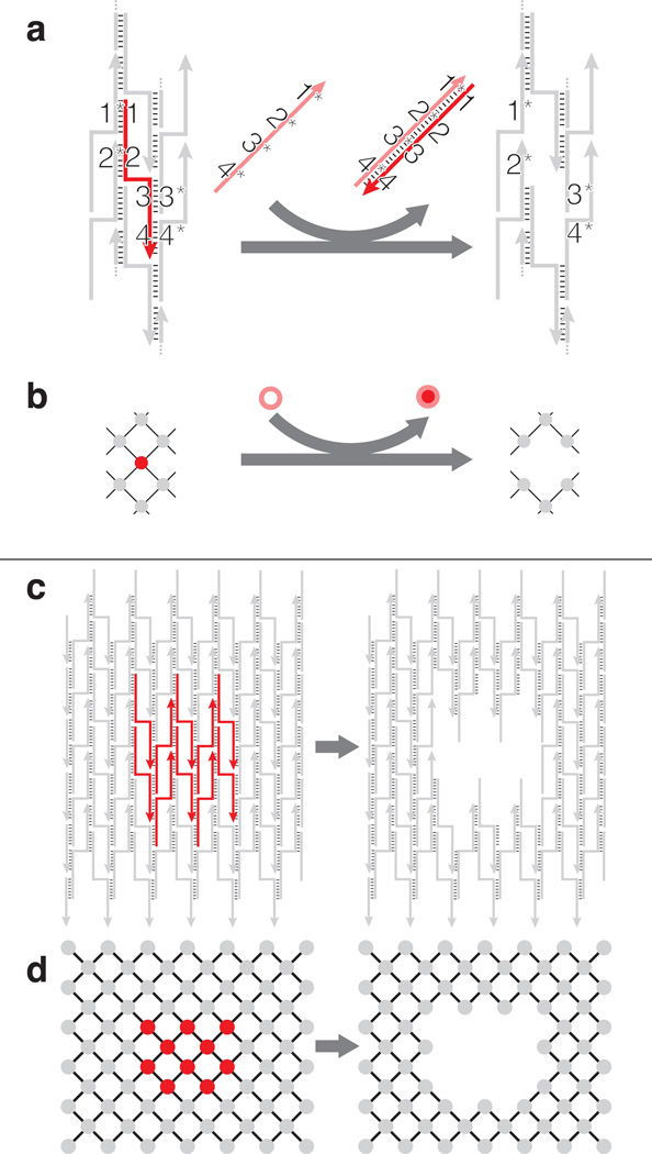
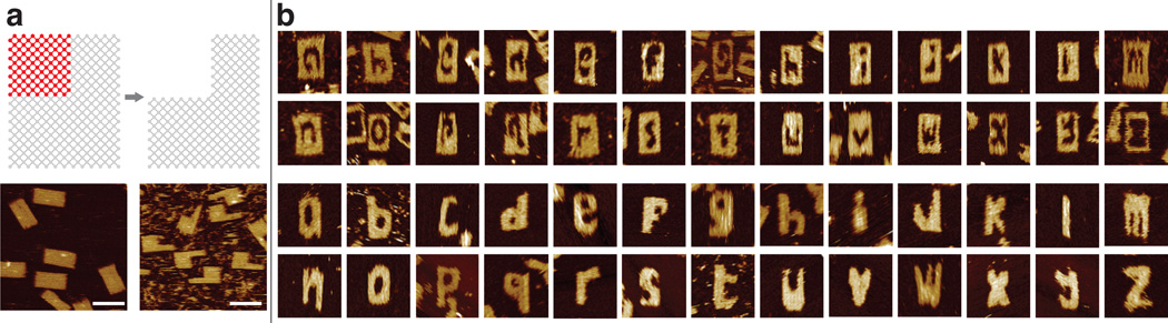
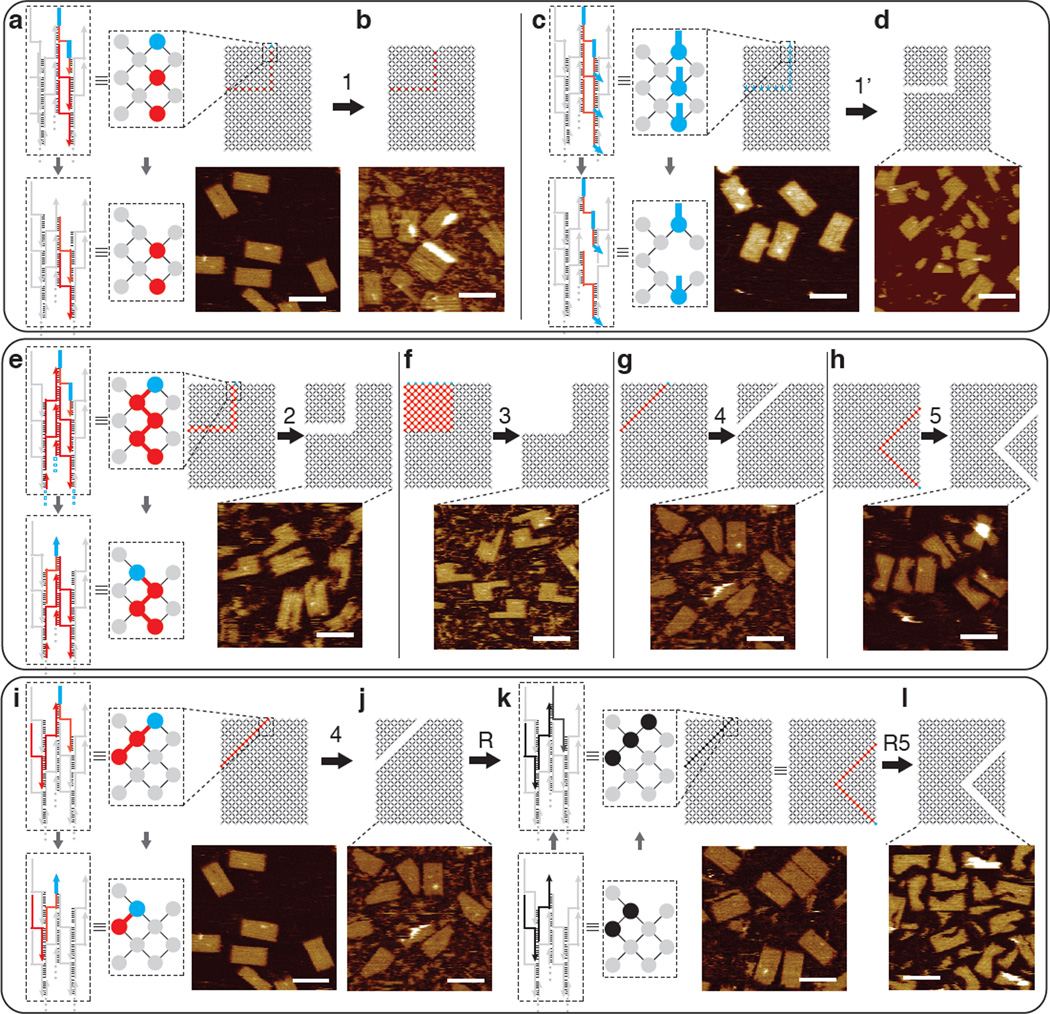
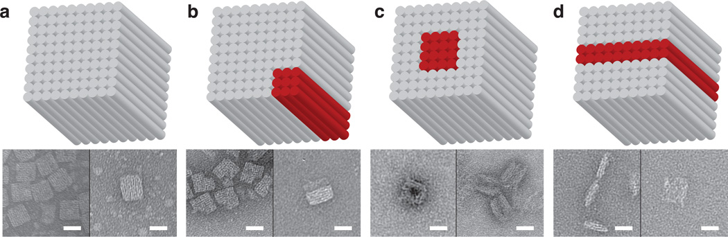
Nucleic acids have been used to create diverse synthetic structural and dynamic systems. Toehold-mediated strand displacement has enabled the construction of sophisticated circuits, motors, and molecular computers. Yet it remains challenging to demonstrate complex structural reconfiguration in which a structure changes from a starting shape to another arbitrarily prescribed shape. To address this challenge, we have developed a general structural-reconfiguration method that utilizes the modularly interconnected architecture of single-stranded DNA tile and brick structures. The removal of one component strand reveals a newly exposed toehold on a neighboring strand, thus enabling us to remove regions of connected component strands without the need to modify the strands with predesigned external toeholds. By using this method, we reconfigured a two-dimensional rectangular DNA canvas into diverse prescribed shapes. We also used this method to reconfigure a three-dimensional DNA cuboid.

Keywords: DNA bricks; nanostructures; single-stranded tiles; strand displacement; structural reconfiguration.


Figures

Figure 1
Figure 1
Schematics of structural reconfiguration from an SST canvas. a) A strand diagram of strand displacement based SST structural reconfiguration and b) the associated interaction graph. The strand/node to be displaced is highlighted in red with four domains 1, 2, 3 and 4 complementary to domains 1*, 2*, 3* and 4* of the neighboring strands, respectively. When introduced to the system, a full complementary strand 4*-3*-2*-1*, in salmon, forms a duplex with the red target component strand to displace the target off the canvas. c) A strand diagram of strand displacement for an 8 helix (H) × 10 turns (T) canvas and d) the associated interaction graph. Strands or nodes high- lighted in red, as shown on the left, depict the subset of component strands to be displaced. The carved structure is shown on the right.
Figure 2
Figure 2
Alphabet sets reconfigured from a rectangular SST canvas. a) Interaction graphs (top) and AFM images (bottom) of the 24H × 29T canvas used in this study (left) and its reconfiguration into a rectangle with a missing corner (right). Scale bars: 100 nm. b) AFM images of alphabet carved in intaglio (top) and relief (bottom). Each image is 150 nm × 150 nm in size. See Figure S4 and Figure S5 for agarose gel electrophoresis results.
Figure 3
Figure 3
Diagrams and AFM images of mechanism study. For all panels, top: interaction graphs with the carving pattern highlighted in red and blue; bottom: AFM images (scale bars: 100 nm). Top panel depicts carving from pattern 1 without predesigned external toeholds (a, b) and pattern 1’ with predesigned external toeholds (c, d). Middle panel (e–h) depicts carving patterns 2–5. Bottom panel (i–l) depicts reversibility of carving: reconfiguration from canvas to pattern 4, to re-assembly, and to pattern R5 (identical to pattern 5). The strand diagram and interaction graph boxed by the dashed lines show the reconfiguration mechanism at the zoomed-in fraction of the canvas (in a), c), e), i) and k)). Grey depicts common components; red depicts the strands without external toeholds to be carved; blue marks the presence of an exposed single-stranded toehold; black indicates the introduction of strands for re-assembling the carved canvas pieces. See SI Sect. S3.1 and S3.3 for detailed study of carving yields.
Figure 4
Figure 4
Structural reconfiguration from a 3D cuboid. Top panel, cylinder model of the cuboid (red cylinders denote the ones to be displaced); bottom panel, TEM images (scale bar: 20 nm). a) Cuboid before structural reconfiguration. b) Carving a corner from the cuboid. c) Carving a tunnel through the cuboid. d) Carving the cuboid into two halves.

Similar articles

Cited by

References

    1. Seeman NC. J. Theor. Biol. 1982;99:237–247. - PubMed
    1. Chen J, Seeman NC. Nature. 1991;350:631–633. - PubMed
    1. Fu TJ, Seeman NC. Biochemistry. 1993;32:3211–3220. - PubMed
    1. Winfree E, Liu F, Wenzler LA, Seeman NC. Nature. 1998;394:539–544. - PubMed
    1. Yan H, Park SH, Finkelstein G, Reif JH, LaBean TH. Science. 2003;301:1882–1884. - PubMed

Publication types

LinkOut - more resources