. 2015 May;73(5):1803-11.
doi: 10.1002/mrm.25300. Epub 2014 Jun 5.

Real-time active MR-tracking of metallic stylets in MR-guided radiation therapy

Affiliations

Real-time active MR-tracking of metallic stylets in MR-guided radiation therapy

Wei Wang et al. Magn Reson Med. 2015 May.

Abstract

Purpose: To develop an active MR-tracking system to guide placement of metallic devices for radiation therapy.

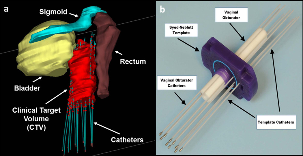
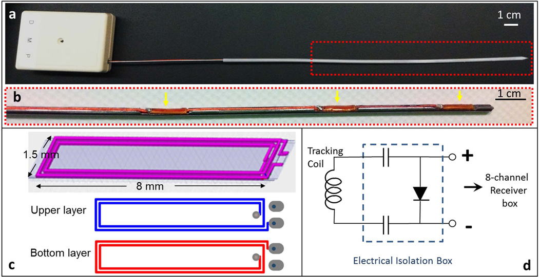
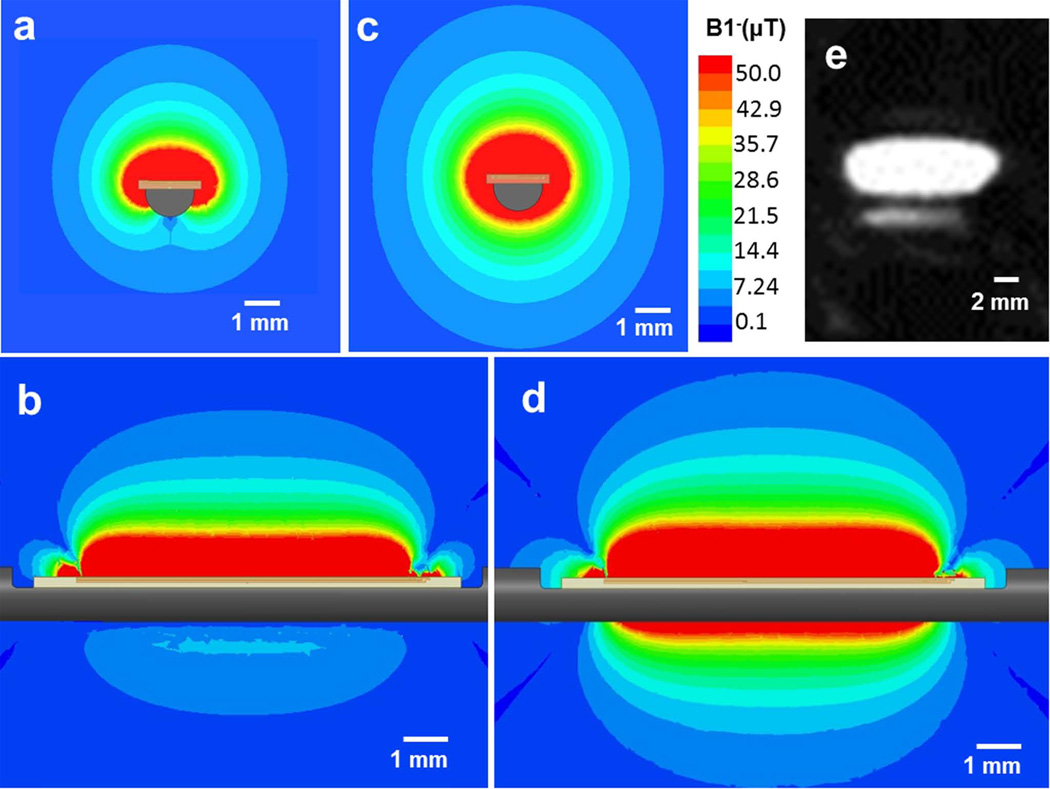
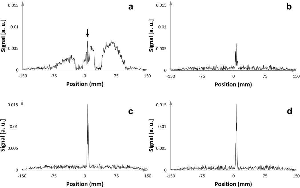
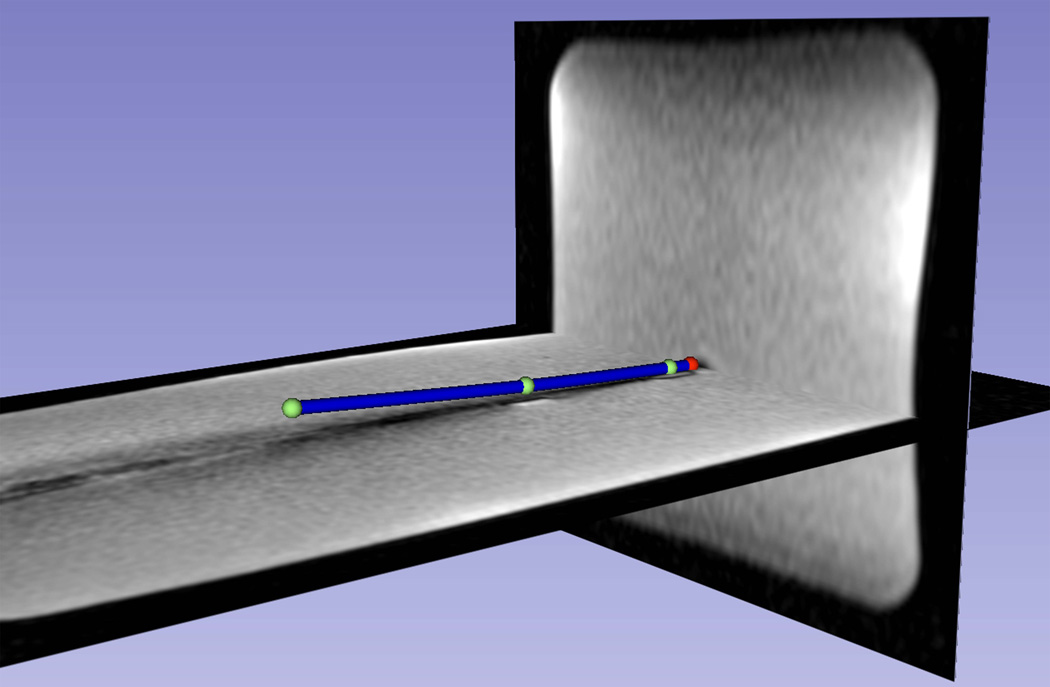
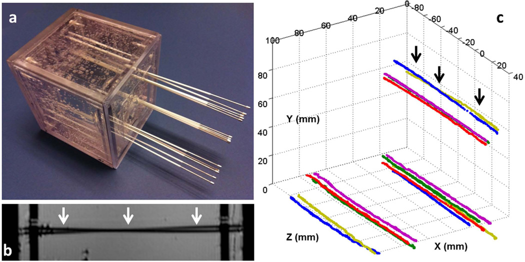
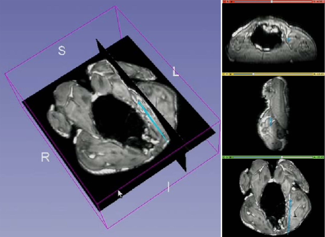
Methods: An actively tracked metallic stylet for brachytherapy was constructed by adding printed-circuit micro-coils to a commercial stylet. The coil design was optimized by electromagnetic simulation, and has a radio-frequency lobe pattern extending ∼5 mm beyond the strong B0 inhomogeneity region near the metal surface. An MR-tracking sequence with phase-field dithering was used to overcome residual effects of B0 and B1 inhomogeneities caused by the metal, as well as from inductive coupling to surrounding metallic stylets. The tracking system was integrated with a graphical workstation for real-time visualization. The 3 Tesla MRI catheter-insertion procedures were tested in phantoms and ex vivo animal tissue, and then performed in three patients during interstitial brachytherapy.

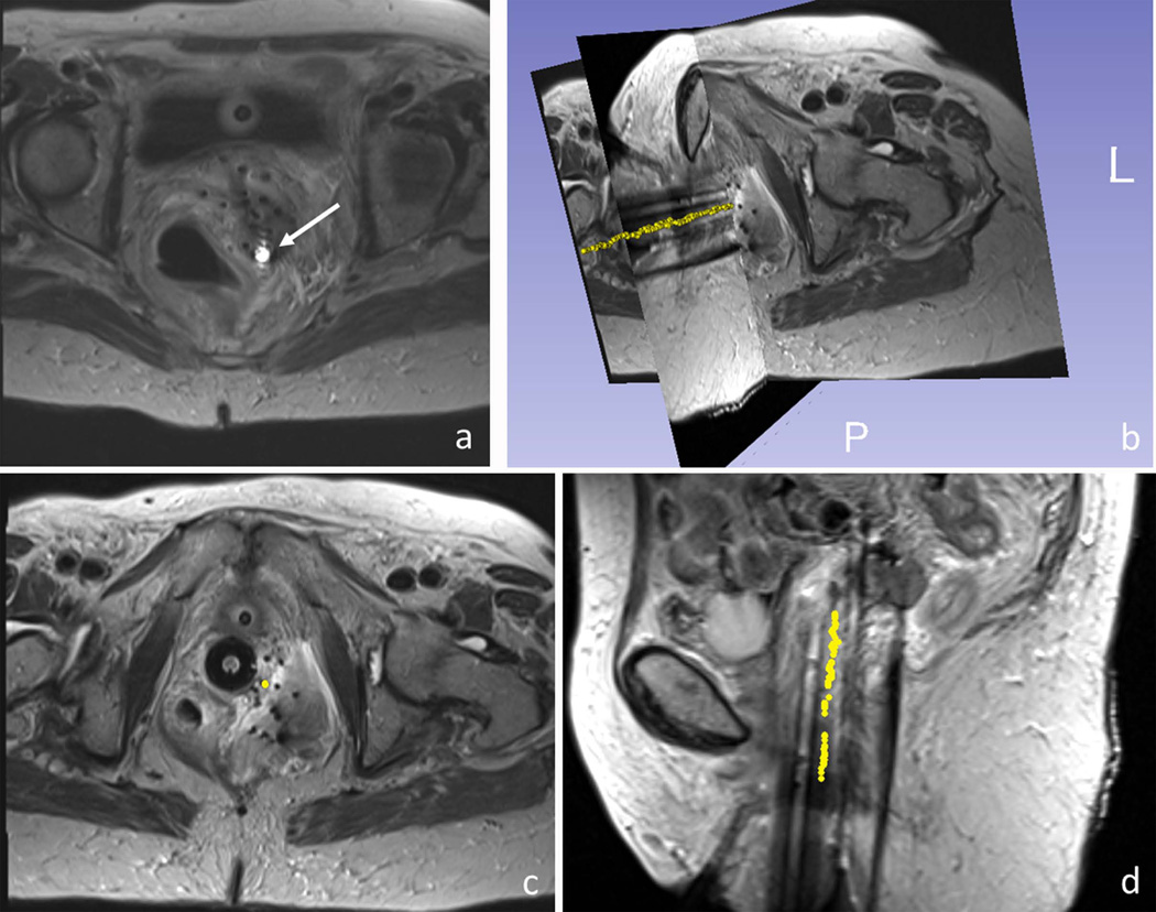
Results: The tracking system provided high-resolution (0.6 × 0.6 × 0.6 mm(3) ) and rapid (16 to 40 frames per second, with three to one phase-field dithering directions) catheter localization in phantoms, animals, and three gynecologic cancer patients.

Conclusion: This is the first demonstration of active tracking of the shaft of metallic stylet in MR-guided brachytherapy. It holds the promise of assisting physicians to achieve better targeting and improving outcomes in interstitial brachytherapy.

Keywords: active MR-tracking; metallic device; phase-field dithering; radiation therapy.


Figures

Figure 1
Figure 1
Gynecologic interstitial brachytherapy procedure: (a) 3D model showing organs at risk surrounding the clinical target volume (CTV). Catheters are introduced to regions around and within the tumor. The plastic catheters are filled with rigid metallic stylets during insertion, but thereafter filled with radioactive sources, with the dwelling points during radiation delivery shown as red spheres. Care must be taken not to puncture the bowel, rectum or bladder dung catheter insertion. (b) Photograph of typical equipment used in an MRI-guided procedure. A template (purple), which is a plastic plate with numerous holes, is sutured onto the patient’s skin. A plastic central obturator (white) is then inserted into the vagina to anchor the assembly in place. Multiple catheters are then placed through designated holes in the template and driven towards prescribed locations.
Figure 2
Figure 2
(a) Photograph of an actively-tracking interstitial brachytherapy catheter, composed of an active metallic stylet, enclosed by a plastic cylindrical cover. The stylet fits into the conventional cover since it has the same external dimensions as a conventional stylet. The white box at the proximal end contains SMB adaptors to connect the three micro-coaxial cables to the receiver box. (b) Enlargement (red dash box in the upper panel) of the distal portion of the active stylet. Three flexible printed circuit (FPC) tracking coils (yellow arrows) were mounted onto the three slots on the surface. (c) Design pattern used in construct of FPC coil. Each coil was built on a double-layered flexible printed circuit sheet, consisting of four rectangular conductive loops. (d) Circuit diagram for each receiver channel in the electrical isolation box (dashed line), which is placed between each micro-coil on the stylet and a single channel in the 8-channel MRI receiver box. The two 0.1 µF capacitors limit leakage currents to less than 10 µA and the pin diode provides the active decoupling signal expected by the receiver.
Figure 3
Figure 3
(a) Axial view (cross-section of the stylet) and (b) sagittal view (along and perpendicular to the shaft) of the B1 EM field simulation with an 8-mm-long micro-coil attached to a metallic stylet. (c) Axial view and (d) sagittal view the B1 EM field simulation with the same micro-coil attached to an insulating stylet. Note that the lobe pattern obtained with the metallic substrate is far smaller than that with the insulating substrate. (e) A high-resolution MR image of a tracking coil mounted on the metallic stylet, acquired with a 3D Turbo Spin Echo sequence. The imaging slice was oriented in the sagittal plane along the active stylet shaft. It demonstrates that strong signal is obtained ~5 mm away from the needle surface.
Figure 4
Figure 4
One-dimensional MR-tracking signal-intensity profiles acquired with an active stylet filled catheter after insertion into the gel phantom, which contained 14 other conventional stylets. (a) Signal intensity profile from acquisition without applying an orthogonal dephasing gradient. In this case, the broad signal from the coupled surrounding stylets overwhelmed the peak from the micro-coil, resulting in the in-ability to obtain the true micro-coil location (the narrow peak highlighted with the black arrow). (b,c) Signal intensity profiles from acquisition with orthogonal PFD gradients applied in two different directions. Some PFD directions were superior in preserving the signal from the micro-coil while suppressing the broad surrounding signals. (d) Tracking signal, achieved by applying a maximum intensity projection to the intensity profiles generated from three different orthogonal dephasing gradients, provided a very high SNR to determine the micro-coil location.
Figure 5
Figure 5
The distal shaft of a slightly bent brachytherapy catheter, which included an active stylet, inside a gel phantom, as visualized on the 3D Slicer workstation. Three coil positions (green spheres) and the extrapolated tip position (red sphere) are shown. The catheters distal shaft (blue cylinder) was reconstructed using a spline fit to the four positions and overlaid on a pre-acquired high-resolution 3D MR image data set, demonstrating the capability of the tracking system to show curvature of the catheter.
Figure 6
Figure 6
(a) Gel phantom with fifteen catheters inserted. All the catheters initially contained conventional stylets within them. A set of five stylets were placed into each of the three corners of the cubic phantom. In each set, three stylets were almost parallel to each other, while two crossed each other. (b) A high-resolution sagittal MR image of the phantom. The two black lines (white arrows) show two catheters that cross each other, which is difficult to identify because it can also represent two touching bent catheters. (c) Fifteen stylet trajectories acquired by capturing the tracked tip position continuously during active stylet pull-out. In all cases, the active tracking system generated stable tracking signal profiles and resolved the trajectories well. Note that two stylets at each of the three corners crossed each other, with the two at the upper corner (black arrows) also shown in b.
Figure 7
Figure 7
Navigation of a catheter including an active stylet in a cleaned chicken, as visualized on the 3D Slicer workstation. The catheters tip’s position and orientation (cyan colored straight lines) were overlaid on pre-acquired high-resolution 3D MR images. Images on right are (top to bottom) axial, sagittal and coronal slices created in real-time at the position of the catheter tip.
Figure 8
Figure 8
MR-guided catheter placement utilizing the active stylet in a gynecologic cancer patient. (a) Active micro-coil (white arrow) was detected on images using an array that included the tracking coils and the MRI’s surface coils. 3D rendering (b) and axial and sagittal views (c,d) of a single active stylet trajectory (yellow dots), overlaid on 3D turbo spin echo images of the patient’s pelvis. The trajectory (yellow points) was reconstructed by consecutively tracking the positions of the catheter tip during stylet pull-out.

References

    1. Cancer facts and figures 2013. 250 Williams Street, NW, Atlanta, GA A 30303-1002: Corporate Center: American Cancer Society Inc.;
    1. Han K, Milosevic M, Fyles A, Pintilie M, Viswanathan AN. Trends in the utilization of brachytherapy in cervical cancer in the United States. International journal of radiation oncology, biology, physics. 2013;87(1):111–119. - PubMed
    1. Viswanathan AN, Cormack R, Holloway CL, Tanaka C, O'Farrell D, Devlin PM, Tempany C. Magnetic resonance-guided interstitial therapy for vaginal recurrence of endometrial cancer. International journal of radiation oncology, biology, physics. 2006;66(1):91–99. - PubMed
    1. Viswanathan AN, Szymonifka J, Tempany-Afdhal CM, O'Farrell DA, Cormack RA. A prospective trial of real-time magnetic resonance-guided catheter placement in interstitial gynecologic brachytherapy. Brachytherapy. 2013;12(3):240–247. - PubMed
    1. Kapur T, Egger J, Damato A, Schmidt EJ, Viswanathan AN. 3-T MR-guided brachytherapy for gynecologic malignancies. Magnetic resonance imaging. 2012;30(9):1279–1290. - PMC - PubMed

Publication types

MeSH terms