Review
. 2014 Aug 28;124(9):1412-25.
doi: 10.1182/blood-2014-05-378638. Epub 2014 Jun 13.

von Willebrand factor, Jedi knight of the bloodstream

Affiliations
Review

von Willebrand factor, Jedi knight of the bloodstream

Timothy A Springer. Blood. .

Abstract

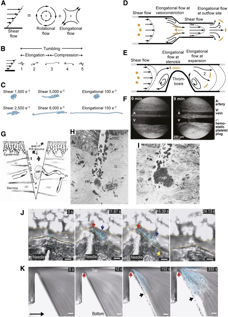
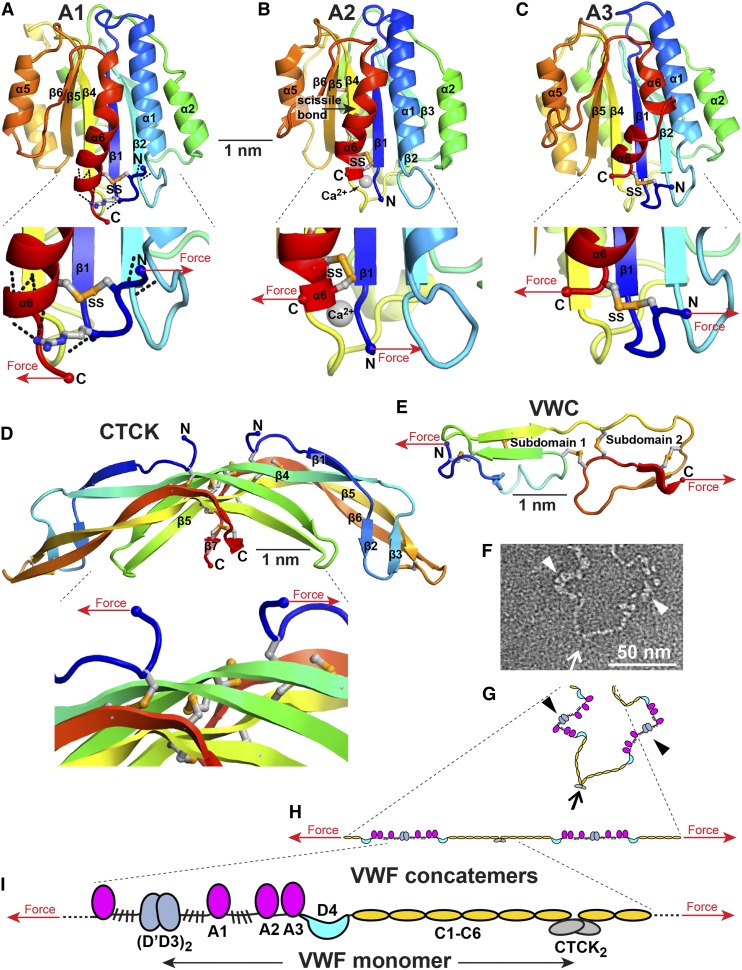
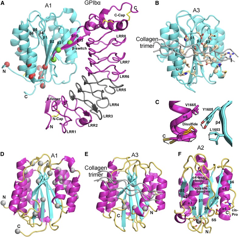
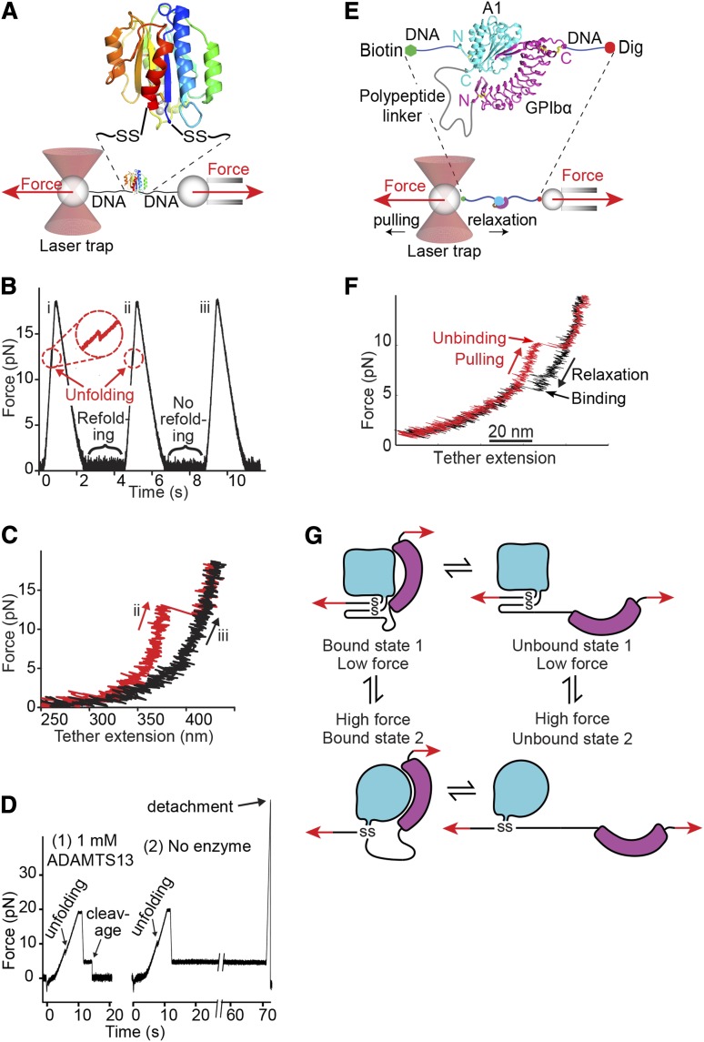
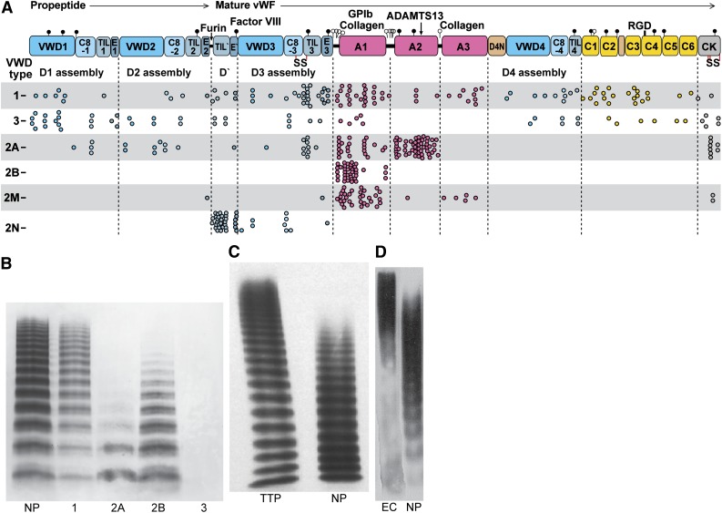
When blood vessels are cut, the forces in the bloodstream increase and change character. The dark side of these forces causes hemorrhage and death. However, von Willebrand factor (VWF), with help from our circulatory system and platelets, harnesses the same forces to form a hemostatic plug. Force and VWF function are so closely intertwined that, like members of the Jedi Order in the movie Star Wars who learn to use "the Force" to do good, VWF may be considered the Jedi knight of the bloodstream. The long length of VWF enables responsiveness to flow. The shape of VWF is predicted to alter from irregularly coiled to extended thread-like in the transition from shear to elongational flow at sites of hemostasis and thrombosis. Elongational force propagated through the length of VWF in its thread-like shape exposes its monomers for multimeric binding to platelets and subendothelium and likely also increases affinity of the A1 domain for platelets. Specialized domains concatenate and compact VWF during biosynthesis. A2 domain unfolding by hydrodynamic force enables postsecretion regulation of VWF length. Mutations in VWF in von Willebrand disease contribute to and are illuminated by VWF biology. I attempt to integrate classic studies on the physiology of hemostatic plug formation into modern molecular understanding, and point out what remains to be learned.


Figures

Figure 1
Figure 1
Mosaic domain structure of VWF. (A) Cysteines are vertical lines and are connected for disulfide bonds assigned chemically,, by structure,, or by homology. N- and O-linked glycans are closed and open lollipops, respectively. Domains are scaled to length and residues are shown with pre-pro numbering. (B-F) D assembly modules. (G-I) A, C, and CTCK domains. Disulfides assigned as described above are connected with colored lines. Secondary structures are overlined and disordered residues are in italics in structurally characterized TIL′, E′, A1,-,, A2,,, A3,,, and CTCK domains. N and O-glycosylated residues and the RGD motif are in red. (J) D′ ribbon diagram with disulfides shown with yellow sulfur atoms.
Figure 2
Figure 2
Biosynthesis and secretion of VWF. (A) Module functions in biosynthesis. (B) Appearance of VWF domains in negative stain EM with class averaging., Two examples of D1D2 and (D′D3A1)2 class averages are shown. A1-CTCK dimeric bouquet class averages, with averaging centered on different domains, are shown in composite, with (D′D3A1)2 added in the position of A1 separated by dashed lines. Domains that would originate from the same VWF dimer precursor are labeled in white, and those that would originate from other dimers and be disulfide linked during concatemer formation in tubules are labeled in yellow. (C-F) Schematic organization of domains during biosynthesis and secretion based on structural data.,,, Dimensions are from Zhou et al and Huang et al.
Figure 3
Figure 3
VWF tubule morphogenesis and structure. (A-B) In vitro assembly of D1D2 and (D′D3)2 fragments at pH 6.2 in Ca2+ into tubules (A) and helical 3-dimensional reconstruction (B) showing external view (right) and a cross-section through the hollow tubule (left) colored from red to blue based on distance from the helical axis. (C) Single tubule in a clathrin-coated immature WPB in the juxta-Golgi. (D-E) Schematic of tubule assembly. Helical assembly is shown as progressing from bottom to top. Each successive pro-VWF dimer is numbered and shown alternately with solid or striped diagonal fill. Interdimer disulfide crosslinks form at the twofold symmetry axis between D′D3 domains (red SS). VWF helices are 1-start, that is, contain a single VWF molecule. Because of twofold symmetry, the 2 ends of the helix are identical. (F) Helical reconstruction from cryoelectron tomography of tubules in endothelial cell WPB (see panels H-I). Panels B and F are aligned vertically to show similar structure of tubules formed in vitro and in vivo. (G) Another example of tubule biogenesis in the juxta-Golgi. (H-I) Cryoelectron tomograms of a mature WPB in an endothelial cell (H) and a reconstruction (I) showing individual tubules (colored). (J) A WPB with increased spacing between tubules and a stalk (arrowhead). The WPB may have been captured during secretion and the stalk may be a secretion pore. (K-L) VWF tubules in porcine platelet α-granules, in EM sections that run parallel (K) or normal (L) to the tubule axis. In contrast to WPB, α-granules contain other components that segregate away from the paracrystalline VWF tubules (T, marked with arrows). (M) A cultured human umbilical vein cell immunofluorescently stained with anti-VWF to visualize WPB. Reprinted from Tom Carter, National Institute of Medical Research, United Kingdom, with permission.
Figure 4
Figure 4
Shear and elongational flows and relation to platelet plug formation and thrombosis. (A) Shear flow, which may be represented as elongational flow superimposed on rotational flow., Arrows show streamlines and dots regions of no flow. (B) Cartoon of VWF elongating, compressing, and tumbling in shear flow. (C) Stills representing the last frame of movies simulating VWF in shear and elongational flows at the indicated rates (supplemental Videos 1-6). VWF is represented as a string of 50 spheres (cyan except for spheres at the 2 ends in magenta). Simulations are similar to those described in Schneider et al and Sing and Alexander-Katz. Simulations and movies are courtesy of Darren Yang and Wesley Wong (Children’s Hospital, Boston, MA). Both shear and elongational flows are measured as velocity/distance and have units of s−1. VWF becomes thread-like at much lower values of elongational flow than shear flow. (D-E) Shear and elongational flows in a bleeding vessel (D) and stenotic vessel (E). Round orange spheres show the effect of elongational flow on the shape of a polymeric protein in the flow field. Two zones of elongational flow marked 1 and 2 are described in “The shape of VWF” section. Elongation of VWF concatemers would occur in the directions shown by the orange globules. (F) Light micrographs of rat mesentery artery (top) and vein (bottom) before and 9 minutes after the wall of the vein was nicked with scissors. Reprinted from Zucker with permission. A platelet plug (arrow) lies above the vein. Vasoconstriction occurs in both the artery and vein and is only seen when a platelet plug is formed, demonstrating that platelet plugs release a diffusible vasoconstrictor. (G-I) Human skin wound experiment for determination of bleeding time. Reprinted from Wester et al with permission. (G) Schematic showing the morphology of the hemostatic plug (HP) formed by a transected vessel (Vs). The plug is 90% outside the vessel. (H-I) Biopsy excised 30 seconds after wounding. Two light micrographs a few sections apart are shown of the same hemostatic plug (HP) formed at the outflow of a transected vessel. D, dermis; E, epidermis; Vs, transected vessel; W, wound. (J-K) Differential interference contrast microscopy of thrombosis formation at sites of vessel constriction in vivo (J) and in vitro (K), reprinted from Nesbitt et al with permission. Flow is left to right. Scale bars are 10 μm. (J) Mouse mesenteric arteriole crush injured with a needle. A platelet aggregate (cyan shading) forms downstream of the injury and stenosis site (red arrow). Blue and yellow arrows mark the center and downstream extent of the platelet aggregate. Time is shown in seconds. After release of the stenosis the aggregate embolized (24 seconds). (K) Whole blood in a microchannel with a 90% stenosis and downstream expansion. Red and black arrows mark the margins of the platelet aggregate (cyan shading). Much less aggregation was noticed with a lower rate of downstream expansion; that is, with lower elongational flow rates.
Figure 5
Figure 5
How VWF and its domains experience force. (A-E) Force on domain termini. Domains are shown in cartoon representation, colored in rainbow from N terminus (blue) to C terminus (red). Disulfides and an Arg in A1 that participates in H bonds are shown in stick with orange sulfurs and blue nitrogens. Arrows show how tensile (elongational) force is exerted across domains when they are present in an elongated VWF concatemer experiencing hydrodynamic force. (A-C) are in similar but slightly different orientations. (A) A1 has a highly conserved set of hydrogen bonds external to the long-range disulfide (black dashes) seen in all crystal structures.-, (B) A2 has a C-terminal, vicinal disulfide bond and a bound Ca2+ ion (silver sphere).,, (C). A3, in contrast to A1, has no hydrogen bonds external to its long-range disulfide, which shows flexibility, with differences in position among structures or disorder.,, (D) The CTCK domain is highly reinforced against elongational force. (E) The VWC domain has no hydrophobic core and flexibility between its 2 subdomains. VWC domains in VWF are not yet characterized at high resolution and are known from collagen IIA and crossveinless 2. (F) Portion of a VWF concatemer at pH 7.4 in negative stain EM. Arrow and arrowheads mark approximate monomer-monomer interfaces at tail-to-tail (arrow) and head-to-head (arrowhead) positions. (G-I) VWF concatemer schematics. (G) interprets the conformation captured in EM in panel F. (H) How the conformation in panel G would be straightened by elongational force. Panel I schematizes at larger scale domain architecture under elongational force.
Figure 6
Figure 6
Structural, binding, and mutational features of A domains. (A-B) The A1 (A) and A3 (B) domains (cyan) in identical orientations bound to GPIbα (magenta) and collagen (silver), respectively. Disulfides are in yellow stick. (A) The A1-GPIbα complex forms a super β-sheet at the interface between the A1 β3 and GPIbα β14 strands. PT-VWD mutations (green Cα atom spheres) stabilize the β-switch in its bound over its unbound conformation. VWD type 2B mutations (red Cα spheres) locate distal from the GPIbα interface, near to the A2 termini where elongational force is applied. VWD type 2B mutations are hypothesized to stabilize an alternative, high-affinity conformation.,, A region of GPIbα that is important for interaction with A1 in high shear and in ristocetin is shown in gray., (B) A3 with collagen bound (silver) shown in identical orientation as A1 in (A) and with collagen-contacting residues shown in stick. A nuclear magnetic resonance structure of A3 bound to fibrillar collagen shows an identical binding site (collagen-perturbed residues shown with Cα atom spheres). (C) Detail of 2 superimposed A2 structures, 1 of which shows a 2 Å outward movement of the C-terminal α6-helix that may mimic an early step in elongational force-induced A2 unfolding. Arrows show direction of movement of key sidechains including scissile residue Tyr1605 and α6-helix regions. C-terminal residue Ser1671 is labeled “C,” arrows show direction of movement from chain A to chain C. (D-E) VWD type 2M mutations, (silver Cα-atom spheres) in A1 (D) and A3 (E), shown in identical orientations. Type 2M mutations are much more numerous and widely distributed in A1. VWD type 2M mutations in A3 locate adjacent to or are buried beneath the collagen binding site. (F) A2 domain structural specializations. The view is rotated almost 180° from that in Figure 5B. Ca2+ is shown as a sphere with coordinating sidechain and backbone carbonyl groups in stick. Isomerization of the cis-peptide bond shown in stick would slow refolding. In C-F, A domain secondary structures are emphasized by their colors: β-strand, cyan; α-helix, magenta; loop, orange yellow. Collagen bound to A3 is shown in silver.
Figure 7
Figure 7
Single-molecule studies on VWF A1 and A2 domains. (A-D) Adapted from Zhang et al with permission. (A) Schematic diagram of how the A2 domain (colored in rainbow as in Figure 5A) is held between 800-bp double-stranded DNA handles and tethered to 2 beads in a laser trap (left) and micropipette (right). DNA is covalently linked through disulfide bridges to Cys residues mutationally added at the N and C termini of A2. DNA handles have biotin and digoxigenin (Dig) tags at opposite ends for binding to beads functionalized with streptavidin and digoxigenin antibody. Force is applied by micropipette movement (right), and measured by bead displacement in the laser trap (left). The sine qua non of single molecule data are measurement of single molecule events; other types of events are recorded and they must be discarded using fiduciary markers. DNA handles provide a single molecule signature, that is, a plateau at 67 pN at a transition from B to S DNA. Furthermore, adsorption to beads, cantilever tips, and substrates is prevented by holding proteins away from them with DNA handles. (B) Three representative cycles of force increase, decrease, and clamping at a constant low level to enable A2 refolding. (C) Traces of force vs tether extension in the force increase phases of cycles ii and iii in panel B. An abrupt unfolding event is seen in ii and not iii. It is inferred that A2 was unfolded at the beginning of iii. (D) Two representative traces showing ADAMTS13 cleavage in presence of enzyme (1) and no cleavage in absence of enzyme (2). In each trace unfolding of A2 is seen, and A2 is returned to a clamped force of 5 pN. Cleavage of the tether returns force to 0. (E-G). Repeated measurement of GPIbα and VWF A1 domain binding and unbinding in a single molecule ReaLiSM construct. Modified from Kim et al with permission. (E) Schematic. The ReaLiSM contains from N to C the A1 domain, a 43-residue polypeptide linker, and GPIbα, and is expressed as a secreted protein in mammalian cells. Cysteines are included at the N and C termini for disulfide linkage to DNA handles, which are coupled to beads as in panel A. (F) One representative cycle. Unbinding and rebinding are measured as abrupt changes in tether extension during pulling (red) and relaxation (black). (G) Schematic model of A1- GPIbα flex-bond. The model reflects 2 different pathways for receptor-ligand dissociation and association (J. S. Kim, N. E. Hudson, and T.A.S., unpublished observations), with a slower dissociating and faster associating state induced by force. A1 (cyan) and GPIbα (magenta) are subjected to tensile force at the N and C termini of the ReaLiSM construct (arrows), and after dissociation, also at the junctions with the polypeptide linker.
Figure 8
Figure 8
VWD and concatemer length distributions. (A) VWF and its domains to scale by amino acid residue with distribution of VWD mutations. Mutations are from the International Society for Thrombosis and Hemostasis Database. Each missense mutation, including mutations of the same residue to different amino acids, is shown as a dot. Mutations are type 1, partial quantitative deficiency; type 2A, reduced platelet adhesion with absence of long multimers; type 2B, increased platelet adhesion; type 2M, qualitative defect in platelet or collagen binding; type 2N, qualitative defect in binding FVIII; type 3, severe quantitative deficiency. (B-D) VWF length distributions shown with SDS-agarose electrophoresis followed by western blotting with anti-VWF. 1, 2A, 2B, and 3, respective VWD types; EC, VWF secreted by histamine-stimulated endothelial cells in vitro (in absence of ADAMTS13); NP, normal plasma; TTP, thrombotic thrombocytopenic purpura. (B) Reprinted from Sadler with permission. (C) Reprinted from Loirat et al with permission. (D) Reprinted from Arya et al with permission.

References

    1. Zhou YF, Eng ET, Nishida N, Lu C, Walz T, Springer TA. A pH-regulated dimeric bouquet in the structure of von Willebrand factor. EMBO J. 2011;30(19):4098–4111. - PMC - PubMed
    1. Zhou YF, Eng ET, Zhu J, Lu C, Walz T, Springer TA. Sequence and structure relationships within von Willebrand factor. Blood. 2012;120(2):449–458. - PMC - PubMed
    1. Wagner DD. Cell biology of von Willebrand factor. Annu Rev Cell Biol. 1990;6:217–246. - PubMed
    1. Sadler JE. New concepts in von Willebrand disease. Annu Rev Med. 2005;56:173–191. - PubMed
    1. Yee A, Kretz CA. Von Willebrand factor: form for function. Semin Thromb Hemost. 2014;40(1):17–27. - PubMed

Publication types

Substances