. 2014 Jun 19:4:5357.
doi: 10.1038/srep05357.

Developing gradient metal alloys through radial deposition additive manufacturing

Affiliations

Developing gradient metal alloys through radial deposition additive manufacturing

Douglas C Hofmann et al. Sci Rep. .

Abstract

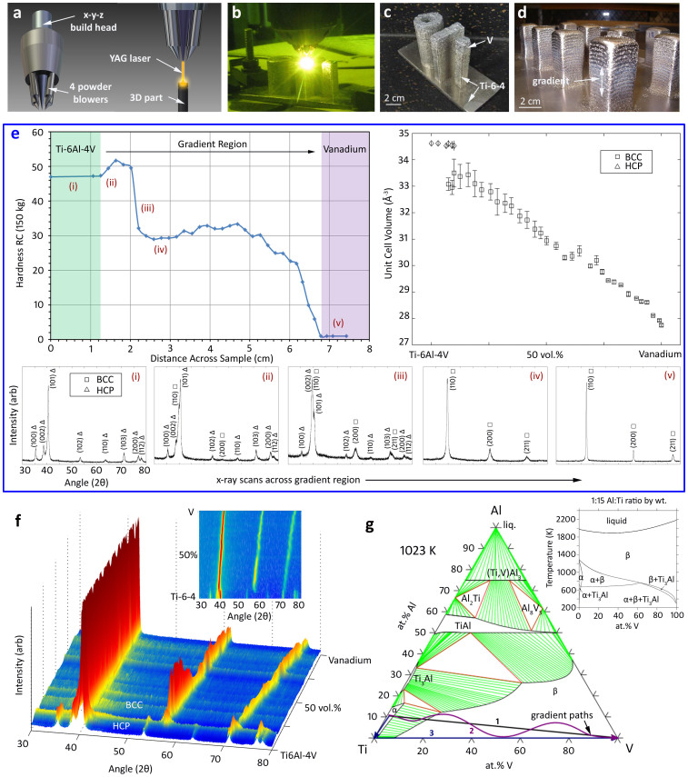
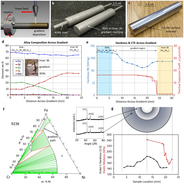
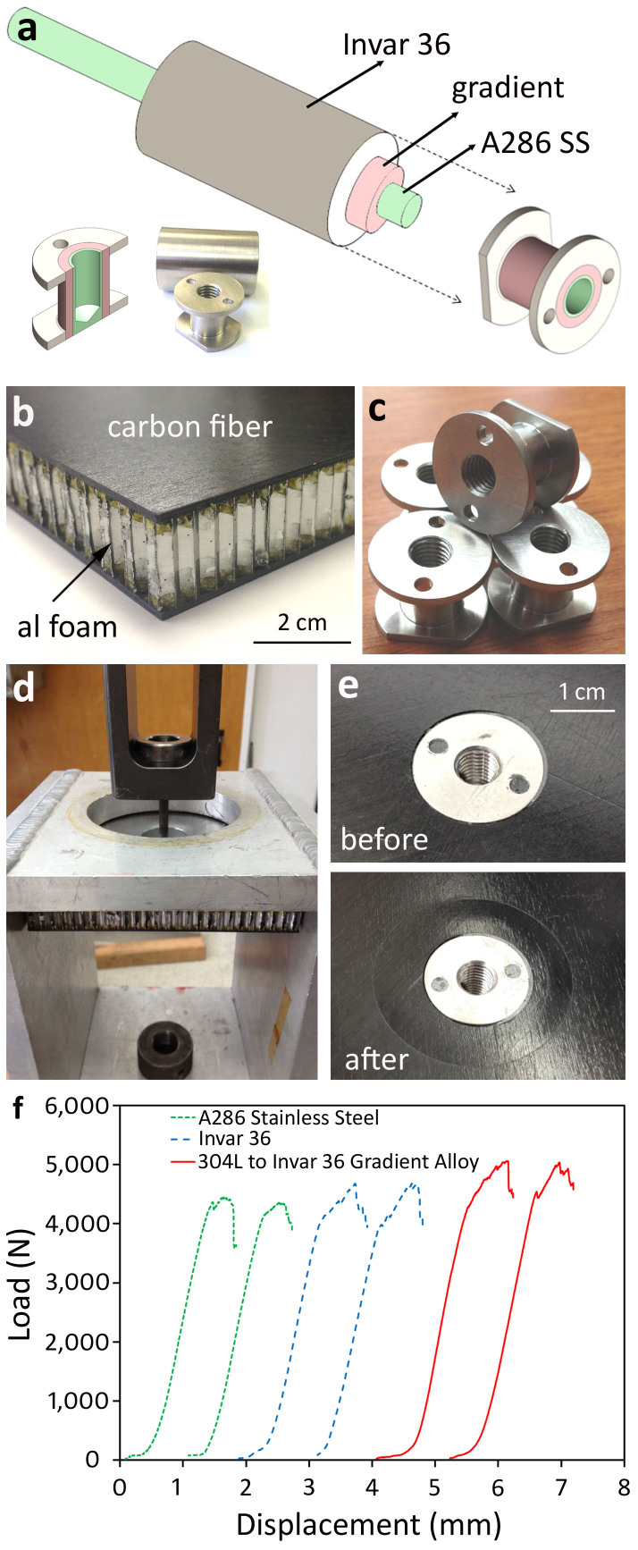
Interest in additive manufacturing (AM) has dramatically expanded in the last several years, owing to the paradigm shift that the process provides over conventional manufacturing. Although the vast majority of recent work in AM has focused on three-dimensional printing in polymers, AM techniques for fabricating metal alloys have been available for more than a decade. Here, laser deposition (LD) is used to fabricate multifunctional metal alloys that have a strategically graded composition to alter their mechanical and physical properties. Using the technique in combination with rotational deposition enables fabrication of compositional gradients radially from the center of a sample. A roadmap for developing gradient alloys is presented that uses multi-component phase diagrams as maps for composition selection so as to avoid unwanted phases. Practical applications for the new technology are demonstrated in low-coefficient of thermal expansion radially graded metal inserts for carbon-fiber spacecraft panels.


Figures

Figure 1
Figure 1. Analyzing a Ti-6Al-4V to V Gradient Alloy.
– (a) Schematic of the laser deposition (LD) building heads used to fabricate gradient alloys. (b) Image of the LD process fabricating several test specimens of the Ti-V gradients. (c) Three gradient alloy specimens; a hollow cylinder, a plate and a beam. (d) Example of a “forest” of gradient alloy posts used to vary gradient compositions. (e) A plot of Rockwell C hardness vs. distance across at Ti-6Al-4V to V gradient alloy where x-ray scans from locations (i–v) are shown below the figure. At right is a plot showing unit cell volume throughout the gradient, as measured from the x-ray peaks. (f) A 3D map of x-ray peaks across the gradient alloy showing the transition from HCP to BCC and the lattice shift of BCC (2D shown in the inset). (g) A Ti-Al-V vertical section at 1023 K. Path (1) is the rule-of-mixtures between Ti-6Al-4V powder and V powder. Path (2) represents a gradient path which transitions from Ti-6Al-4V to pure Ti then to pure V. Path (3) is meant to illustrate a freeform path, where the composition can be changed continuously by mixing Ti, Al and V elemental powder.
Figure 2
Figure 2. Developing a radially graded alloy.
– (a) Schematic of the rotational deposition process used to develop alloys with gradient compositions in a radial direction. (b) Image of two radially graded alloys where a 304 L to Invar 36 gradient was applied to a rotating A286 stainless steel rod. (c) After removal of 1.5 mm of surface layer, a fully dense gradient rod is obtained. (d) A plot of composition vs. distance for a 304 L to Invar 36 gradient alloy post. (e) A plot of Rockwell B hardness and coefficient of thermal expansion vs. distance for the gradient alloy from (d). Solid red lines connect experimental measurements and dashed lines are theoretical estimates. (f) A calculated phase diagram at 923 K showing a “gradient path” from 304 L to Invar 36. (g) Nanoindentation on the gradient rod shown in (b–c) showing Vickers hardness and modulus (utilizing the same axis). X-ray scans are shown in the insets for two locations near the gradient.
Figure 3
Figure 3. Gradient Alloys for Carbon Fiber Composite Inserts.
– (a) Schematic of how gradient inserts were machined from a radially graded rod, shown in Fig. 2. (b) Enlargement of a carbon fiber/aluminum honeycomb commonly used in spacecraft applications. (c) Examples of identical inserts machined from the gradient alloy, pure Invar and pure A286 steel. (d) Pull-out testing for the low-temperature cycled inserts that have been attached to the panel using epoxy. (e) Before and after images of the insert pull-out tests, showing deformation in the carbon fiber panel. (f) Load vs. displacement curves for the pull-out tests showing that the gradient insert outperformed the monolithic metal ones.

References

    1. Hopkinson N., Hague R. & Dickens P. Rapid manufacturing: an industrial revolution for a digital age. (Wiley-Blackwell, Berlin, 2005).
    1. Hague R. J. M., Campbell R. I. & Dickens P. M. Implications on design of rapid manufacturing. Proc. Inst. Mech. Eng. Part C: J. Mech. Eng. Sci. 217, 25–30 (2003).
    1. Campbell R. I., Hague R. J. M., Sener B. & Wormald P. W. The potential for the bespoke industrial designer. The Des. J. 6, 24–34 (2003).
    1. Gibson I., Rosen D. W. & Stucker B. Additive manufacturing technologies: rapid prototyping to direct digital manufacturing. (Springer, London, 2010).
    1. Santos E. C., Shiomi M., Osakada K. & Laoui T. Rapid manufacturing of metal components by laser forming. Int. J. of Mach. Tools and Manuf. 46, 1459–1468 (2006).

Publication types