. 2014 Jul 7:5:4328.
doi: 10.1038/ncomms5328.

Mesoscale assembly of chemically modified graphene into complex cellular networks

Affiliations

Mesoscale assembly of chemically modified graphene into complex cellular networks

Suelen Barg et al. Nat Commun. .

Abstract

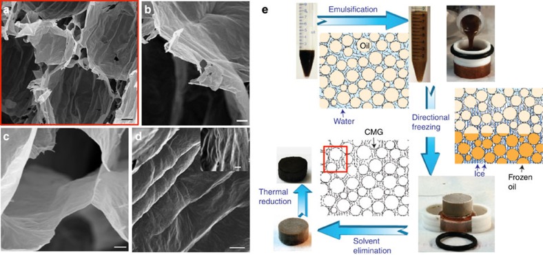
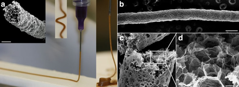
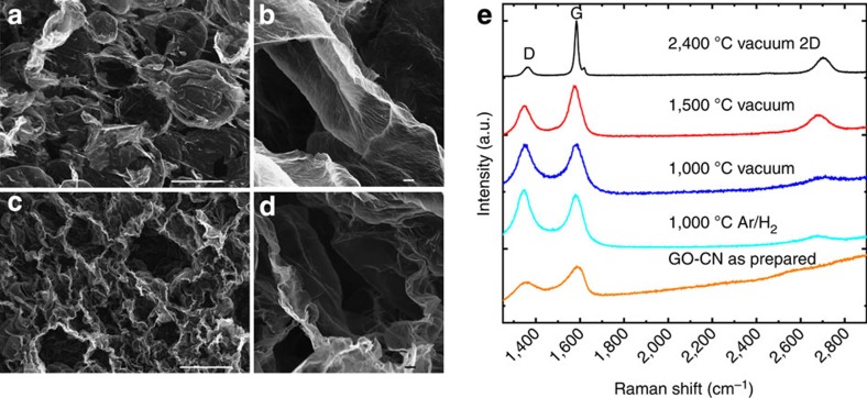
The widespread technological introduction of graphene beyond electronics rests on our ability to assemble this two-dimensional building block into three-dimensional structures for practical devices. To achieve this goal we need fabrication approaches that are able to provide an accurate control of chemistry and architecture from nano to macroscopic levels. Here, we describe a versatile technique to build ultralight (density ≥1 mg cm(-3)) cellular networks based on the use of soft templates and the controlled segregation of chemically modified graphene to liquid interfaces. These novel structures can be tuned for excellent conductivity; versatile mechanical response (elastic-brittle to elastomeric, reversible deformation, high energy absorption) and organic absorption capabilities (above 600 g per gram of material). The approach can be used to uncover the basic principles that will guide the design of practical devices that by combining unique mechanical and functional performance will generate new technological opportunities.


Figures

Figure 1
Figure 1. Microstructural architecture and assembly strategy of CMG-CNs.
(a) Overview of the CMG-CN architecture, composed of nearly spherical pores in the micrometre scale, designed by the emulsion droplet templates. Thin CMG self-assembly: at the pore walls as a result of their entrapment at the interface between water and oil droplets during emulsification (b) and at the triple junction between adjacent cells, whose arrangement is template by ice (c). Cell walls surface micro to nanorugosity patterned by the ice crystals during unidirectional freezing (d). SEM images of 5.6 mg cm−3 GO-CN (ad) that after thermal reduction at 1,000 °C results in rGO-CN of 2.2 mg cm−3. (e) Assembly strategy of CMG-CNs and their structural evolution from emulsification, unidirectional freezing to freeze drying. Following the arrows: As-prepared aqueous GO suspensions (GO-sus) are emulsified with 75 vol% of the hydrophobic internal phase (toluene) resulting in GO emulsions (GO-em) composed by oil droplets dispersed in the GO aqueous continuous phase. GO flakes act as a surface-active amphiphile self-assembling at the oil/water interface. GO-em are moulded into cylindrical shaped moulds and subsequently directionally frozen. As unidirectional freezing of GO-em progresses the ice crystals in the water phase encapsulate liquid oil droplets (as their solidification temperature is much lower) templating the roughness of CMG at the droplet wall. After eliminating the solvents during freeze drying GO-CNs are obtained with the ice and emulsion droplet templating the cellular architecture (ad). rGO-CN are obtained after thermal annealing. Scale bars, 10 μm (a), 2 μm (b), 1 μm (c) and 2 μm (d).
Figure 2
Figure 2. CMG-CN wires.
The viscoelastic properties of the GO emulsion system developed in this work enables its extrusion through micro needles resulting in GO emulsion wires that maintain their shape (straight, curved or spirals) (a) and can be further processed by the approach described in this paper. In (bd) details of rGO-CN wire and internal cellular microstructure after thermal treatment at 1,000 °C in Ar/H2 atmosphere. GO emulsions prepared by the emulsification of 65 vol% decane in 1 wt% GO suspensions containing 1.2 wt% organic additives (1:1, PVA:sucrose). The wires are several centimeters long and down to 200 μm in diameter. Scale bars, 200 μm (a), 300 μm (b), 20 μm (c) and 10 μm (d).
Figure 3
Figure 3. Effect of additives on CMG-CNs microstructure and crystallinity.
SEM images of: GO-CNs produced without (3.3 mg cm−3 density, 65 μm average cell size) (a) and with the addition of 5 wt% organic additives (PVA:sucrose, 1:1 wt%) in 0.65 wt% GO-sus (15 mg cm−3 density, 40 μm average cell size) (b); rGO-CNs thermal treated at 1,000 °C in Ar/H2 atmosphere produced without (1 mg cm−3 density, 63 μm average cell size) (c) and with the addition of 5 wt% organic additives (112 mg cm−3 density, 7 μm average cell size) (d). Shrinkage during the thermal treatment results in highly wrinkled rGO at the cell walls (d). The corresponding Raman spectra (514 nm laser) and C1s XPS of rGO-CNs (prepared without and with organic additives (SEM in c,d)) are represented in e and f, respectively. The letter ‘D’ and ‘G’ stand for two characteristic Raman active modes for graphene and other carbon allotropes and the D/G ratio is a measure of the density of defects present in the carbon material. The C1s XPS spectra (hν=1,253.6 eV) collected on rGO-CN with 5 wt% additives is indicated in red colour whereas the rGO-CN produced without organic additives appears in blue colour. The C1s spectrum collected on rGO-CN with 5 wt% additives was fit by Doniach–Sunjic function after subtracting a Shirley background as indicated in the lowermost spectrum. The different components related to various chemical shifts of carbon bonds are indicated. The component at 284.6 eV is due to the sp2 carbon, the peak at 286.5 eV is related to the remaining C–O bonding and possible carbon sp3 defects, and the component at 287.8 eV is related to residual C=O bonding. The full width at half maximum (FWHM) for the C1s core level for rGO-CNs, with initially 5 wt% additives is narrower than for rGO-CNs without additives. This reflects the different sp2 content, which is about 82% in rGO-CNs, with initially 5 wt% additives (before reduction) and about 80% in rGO-CNs, produced without additives. Scale bars, 100 μm (a,b), 10 μm (c,d) and 2 μm (insert image in d). a.u., arbitrary unit.
Figure 4
Figure 4. Effect of the thermal treatment temperature and atmosphere on rGO-CNs microstructure and crystallinity.
SEM images of rGO-CNs thermally treated in a graphite furnace under high vacuum at: 1,000 °C (a,b) (1.4 mg cm−3 density) and 2,400 °C (c,d) (7.2 mg cm−3 density). The density of as-prepared GO-CNs (0.65 wt% GO and 0.3 wt% additives (PVA:sucrose in 1:1 wt%) in suspension) before thermal treatment is 2.9–3.3 mg cm−3. rGO-CNs reduced at 2,400 °C present highly wrinkled cell walls (c,d) as a result of the high degree of shrinkage (87%) during thermal treatment. (e) Raman spectra of the CMG-CNs as prepared and under different thermal treatments in Ar/H2 atmosphere or in vacuum in a graphite furnace. The Raman spectrums were obtained using 514 nm laser. The letter ‘D’ and ‘G’ stand for two characteristic Raman active modes for graphene and other carbon allotropes and the D/G ratio is a measure of the density of defects present in the carbon material. Scale bars, 100 μm (ac) and 2 μm (bd). a.u., arbitrary unit.
Figure 5
Figure 5. STEM, EELS and N2 adsorption isotherms for ultralight rGO-CNs.
(a,b) STEM HAADF images of an rGO-CNs cell wall. The pores appear in darker contrast on the brighter background of the rGO-CNs. High magnification image (from the region indicated in a reveals mainly mesopores with sizes ranging between ~2 and 10 nm (b). The nanoporosity decorates the rGO-CN restored sp2 network as shown by EELS characterization for rGO-CNs and graphite (c). By comparing the K near-edge structure of both materials, a fraction of 95% of sp2 bonding is found (d). N2 adsorption curve for rGO-CN with 431 m2 g−1 SSA (structure prepared with no additives) and 180 m2 g−1 SSA (structure prepared with 1.2 wt% additives). Scale bars, 0.2 μm (a) and 10 nm (b). a.u., arbitrary unit.
Figure 6
Figure 6. Multicycle compressive properties of rGO-CNs and their properties as a function of density.
(a) Stress-strain curves of rGO-CN (6.1 mg cm−3) showing 98 and 95% recoverable deformation after one and 10 cycles of compression, respectively. rGO-CN was produced with the addition of 1.2 wt% additives (PVA:sucrose 1:1 wt%) to the GO suspension and thermally treated at 300 °C in Ar/H2. (b) Stress-strain curves of an rGO-CN with 17 mg cm−3 showing a plateau characteristic for micro-fracture events similar to those observed in the compression of elastic-brittle foams. This material shows 98 and 94% recoverable deformation after the first and tenth cycles of compression, respectively. The rGO-CN was produced with the addition of 2.5 wt% additives (PVA:sucrose 1:1 wt%) to the GO suspension and thermally treated at 1,000 °C in Ar/H2. (c) Young’s modulus E and (d) collapse stress versus density ρ for rGO-CNs and several low-density carbon-based porous materials reported in literature. An empirical power law fitting (red line) results in an exponent that is significantly lower (1.3) than those reported for other porous carbon structures (2.3–4.6) and the quadratic dependence expected for an open cell. The data have also been fitted to the E=aρ2+bρ equation resulting from the theoretical analysis of Gibson and Ashby (black dashed line) for a closed-cell foam. The fittings suggest that the rGO-CNs behaviour is closer to a closed-cell system where the cell wall membrane stresses have a significant role. The criteria used to calculate the collapse stresses is shown in a and b. formula image 
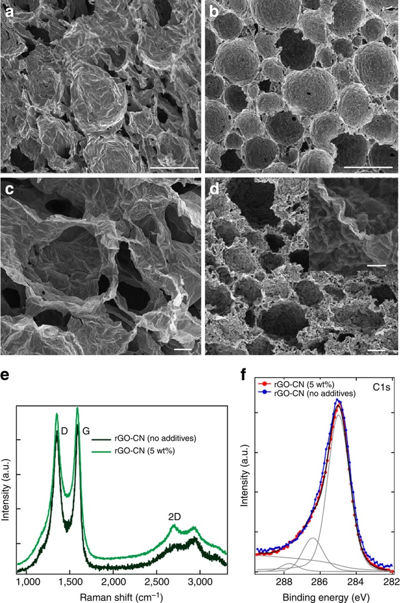
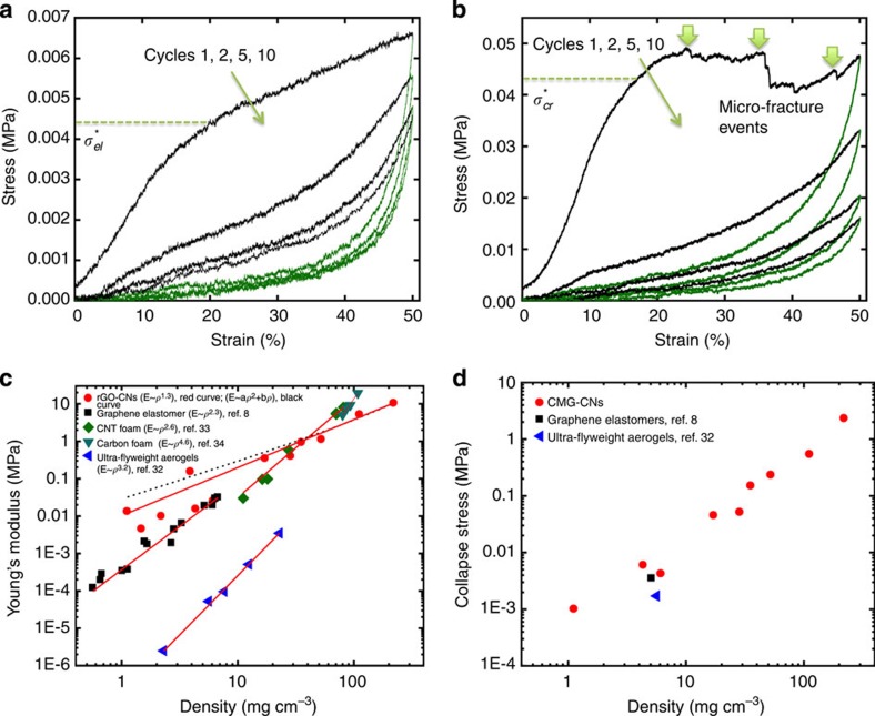
represents the elastic collapse stress (characteristic for lighter materials) and formula image the brittle collapse stress characteristic for denser rGO-CNs.
Figure 7
Figure 7. Electrical conductivity of rGO-CNs as a function of density together with several low-density carbon nanomaterials reported in the literature.
The data correspond to rGO-CNs with different densities (produced with the addition of 0.3 or 1.2 wt% additives in the GO-sus) after being thermally treated in vacuum (graphite furnace) between 1,000 and 2,400 °C (annealing temperature identified in the data points).
Figure 8
Figure 8. rGO-CNs capability for organics absorption, wetting behaviour and recycling approach.
(a) The rGO-CN floats when in contact with water due to its superhydrophobic properties. Water droplet forms a contact angle of 114° with the rGO-CN surface (insert). (b) rGO-CN rapidly absorbs gasoline filling the highly porous structure with the solvent resulting on its immersion in the gasoline vial. In the insert, gasoline trace left after infiltration in the rGO-CN. (c,d) Recycling approach for rGO-CNs absorbers. After each absorption cycle, the oil phase can be ‘squeezed out’ of the rGO cellular absorber by compressing it (c) and the compressed structure can be directly re-utilized by immersing it in the oil phase again. The absorber immediately expands to its original shape by the absorption of the oil phase within its structure (d) (details in Supplementary Movie). (e) Organics absorption (g g−1) of rGO-CNs in comparison with several absorbers reported in literature for different organic solvents and oils. The rGO cellular absorbers tested (4–4.5 mg cm−3) were produced with 1.2 wt% additives in GO-sus (0.65 wt% GO) and thermally treated at 1,000 °C in Ar/H2 atmosphere.

References

    1. Geim A. K. & Novoselov K. S. The rise of graphene. Nat. Mater. 6, 183–191 (2007). - PubMed
    1. Stoller M. D., Park S., Zhu Y., An J. & Ruoff R. S. Graphene-based ultracapacitors. Nano Lett. 8, 3498–3502 (2008). - PubMed
    1. Ghosh S. et al. Extremely high thermal conductivity of graphene: Prospects for thermal management applications in nanoelectronic circuits. Appl. Phys. Lett. 92, 151911 (2008).
    1. Gómez-Navarro C. et al. Electronic transport properties of individual chemically reduced graphene oxide sheets. Nano Lett. 7, 3499–3503 (2007). - PubMed
    1. Chen Z. P. et al. Three-dimensional flexible and conductive interconnected graphene networks grown by chemical vapour deposition. Nat. Mater. 10, 424–428 (2011). - PubMed

Publication types