

Nanoporous anodic alumina platforms: engineered surface chemistry and structure for optical sensing applications
- PMID: 25004150
- PMCID: PMC4168464
- DOI: 10.3390/s140711878
Nanoporous anodic alumina platforms: engineered surface chemistry and structure for optical sensing applications
Abstract
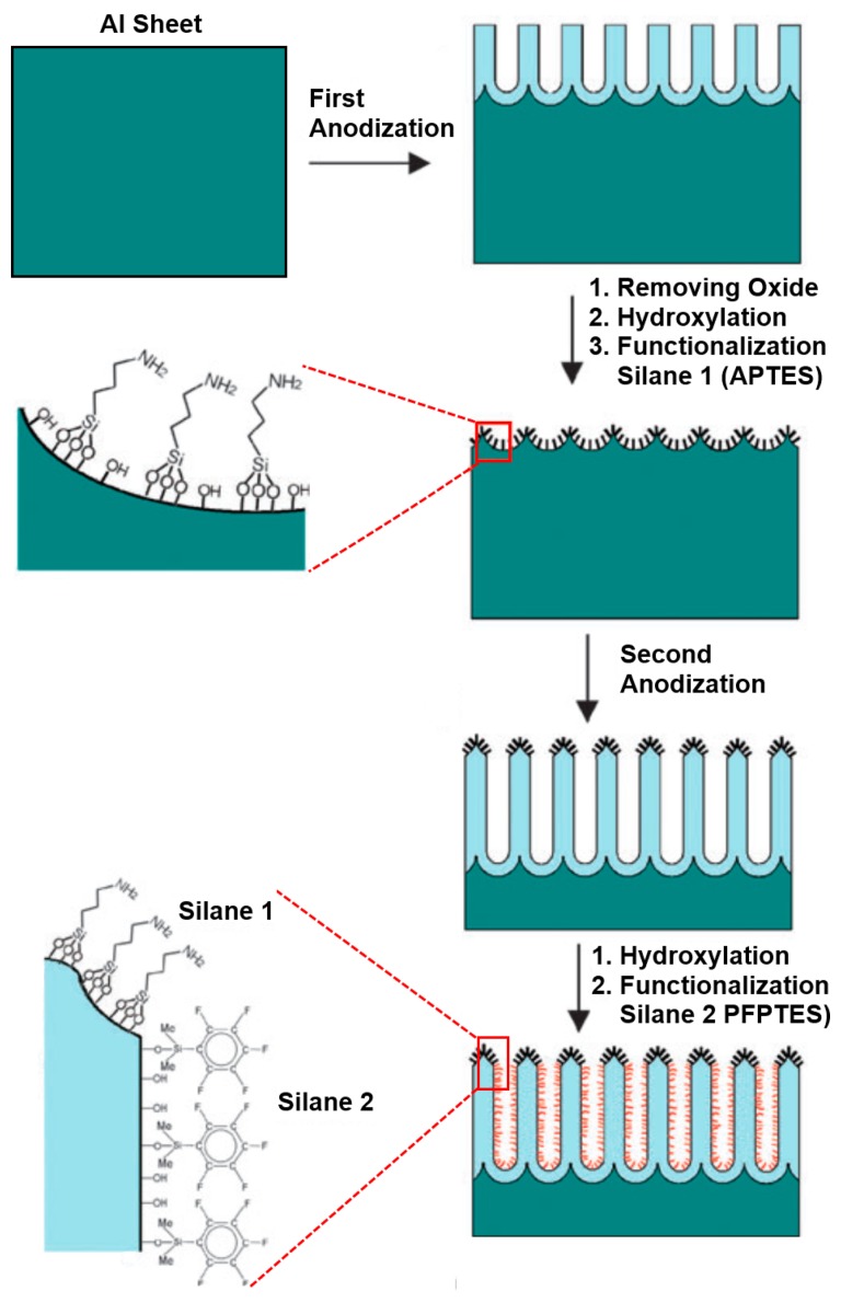
Electrochemical anodization of pure aluminum enables the growth of highly ordered nanoporous anodic alumina (NAA) structures. This has made NAA one of the most popular nanomaterials with applications including molecular separation, catalysis, photonics, optoelectronics, sensing, drug delivery, and template synthesis. Over the past decades, the ability to engineer the structure and surface chemistry of NAA and its optical properties has led to the establishment of distinctive photonic structures that can be explored for developing low-cost, portable, rapid-response and highly sensitive sensing devices in combination with surface plasmon resonance (SPR) and reflective interference spectroscopy (RIfS) techniques. This review article highlights the recent advances on fabrication, surface modification and structural engineering of NAA and its application and performance as a platform for SPR- and RIfS-based sensing and biosensing devices.
Figures
Similar articles
-
Biomimetic Nanoporous Anodic Alumina Distributed Bragg Reflectors in the Form of Films and Microsized Particles for Sensing Applications.ACS Appl Mater Interfaces. 2015 Sep 9;7(35):19816-24. doi: 10.1021/acsami.5b05904. Epub 2015 Aug 26. ACS Appl Mater Interfaces. 2015. PMID: 26287736
-
The influence of nanopore dimensions on the electrochemical properties of nanopore arrays studied by impedance spectroscopy.Sensors (Basel). 2014 Nov 11;14(11):21316-28. doi: 10.3390/s141121316. Sensors (Basel). 2014. PMID: 25393785 Free PMC article.
-
Real-Time Detection of Human Growth Hormone Based on Nanoporous Anodic Alumina Interferometric Biosensor.Sensors (Basel). 2025 Feb 9;25(4):1021. doi: 10.3390/s25041021. Sensors (Basel). 2025. PMID: 40006250 Free PMC article.
-
Advances in Nanoporous Anodic Alumina-Based Biosensors to Detect Biomarkers of Clinical Significance: A Review.Adv Healthc Mater. 2018 Mar;7(5). doi: 10.1002/adhm.201700904. Epub 2017 Dec 5. Adv Healthc Mater. 2018. PMID: 29205934 Review.
-
Recent advances in plasmonic sensors.Sensors (Basel). 2014 May 5;14(5):7959-73. doi: 10.3390/s140507959. Sensors (Basel). 2014. PMID: 24803189 Free PMC article. Review.
Cited by
-
Synthesis and Characterization of Ru-Loaded Anodized Aluminum Oxide for Hydrogenation Catalysis.ChemistryOpen. 2019 Apr 16;8(4):532-538. doi: 10.1002/open.201900091. eCollection 2019 Apr. ChemistryOpen. 2019. PMID: 31061778 Free PMC article.
-
Scanning Kelvin Probe Microscopy: Challenges and Perspectives towards Increased Application on Biomaterials and Biological Samples.Materials (Basel). 2018 Jun 5;11(6):951. doi: 10.3390/ma11060951. Materials (Basel). 2018. PMID: 29874810 Free PMC article. Review.
-
Optical Properties of Porous Alumina Assisted Niobia Nanostructured Films-Designing 2-D Photonic Crystals Based on Hexagonally Arranged Nanocolumns.Micromachines (Basel). 2021 May 21;12(6):589. doi: 10.3390/mi12060589. Micromachines (Basel). 2021. PMID: 34063841 Free PMC article.
-
Structurally Different Yet Functionally Similar: Aptamers Specific for the Ebola Virus Soluble Glycoprotein and GP1,2 and Their Application in Electrochemical Sensing.Int J Mol Sci. 2023 Feb 27;24(5):4627. doi: 10.3390/ijms24054627. Int J Mol Sci. 2023. PMID: 36902059 Free PMC article.
-
Surface Functionalized Anodic Aluminum Oxide Membrane for Opto-Nanofluidic SARS-CoV-2 Genomic Target Detection.IEEE Sens J. 2021 Aug 31;21(20):22645-22650. doi: 10.1109/JSEN.2021.3109022. eCollection 2021 Oct 15. IEEE Sens J. 2021. PMID: 35789083 Free PMC article.
References
-
- Gyurcsányi R.E. Chemically-modified nanopores for sensing. TrAC Trends Anal. Chem. 2008;27:627–639.
-
- Santos A., Kumeria T., Losic D. Nanoporous anodic aluminum oxide for chemical sensing and biosensors. TrAC Trends Anal. Chem. 2013;44:25–38.
-
- Ingham C.J., ter Maat J., de Vos W.M. Where bio meets nano: The many uses for nanoporous aluminum oxide in biotechnology. Biotechnol. Adv. 2012;30:1089–1099. - PubMed
-
- Velleman L., Triani G., Evans P.J., Shapter J.G., Losic D. Structural and chemical modification of porous alumina membranes. Microporous Mesoporous Mater. 2009;126:87–94.
Publication types
MeSH terms
Substances
LinkOut - more resources
Full Text Sources
Other Literature Sources
Miscellaneous
