

doi: 10.3390/s140814858.
Implantable impedance plethysmography
Affiliations
- PMID: 25123467
- PMCID: PMC4179001
- DOI: 10.3390/s140814858
Item in Clipboard
Implantable impedance plethysmography
Sensors (Basel).
.
Abstract
We demonstrate by theory, as well as by ex vivo and in vivo measurements that impedance plethysmography, applied extravascularly directly on large arteries, is a viable method for monitoring various cardiovascular parameters, such as blood pressure, with high accuracy. The sensor is designed as an implant to monitor cardiac events and arteriosclerotic progression over the long term.
Figures
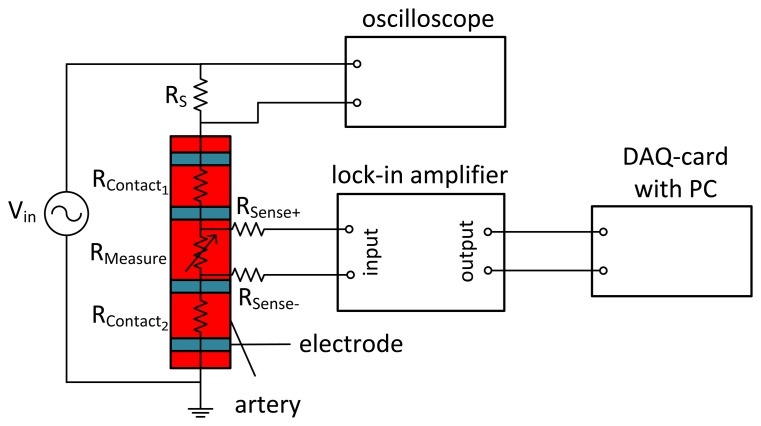
Four-wire measurement of arterial impedance. An alternating voltage (f = 100 kHz) is applied to the outer source electrodes. The voltage at the sense electrodes, demodulated by the lock-in amplifier, is only influenced by the impedance of the artery.
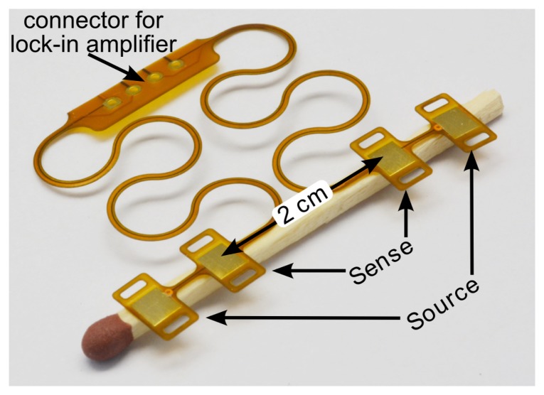
Flexible polyimide foil with four electrodes to be placed on an artery. The meander structure makes the connection stretchable.
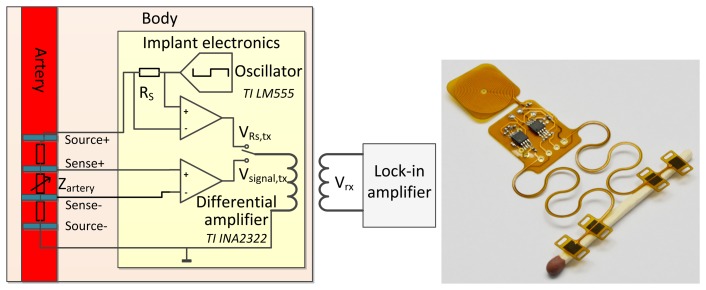
(Left) Schematic of a battery-powered implantable version of the impedance plethysmography (IPG) sensor. The modulated voltage at the sense contacts is conditioned by a differential amplifier and inductively coupled to the extracorporeal lock-in amplifier. (Right) Photograph of this circuit, realized on flexible polyimide foil.
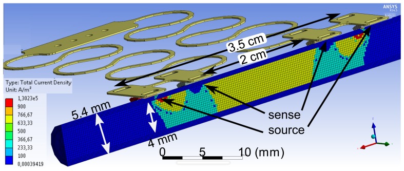
FEM simulation of the current density inside an artery of a 4-mm diameter with a vessel wall thickness of 700 μm. A current of 10 mA is fed to the outer source electrodes.
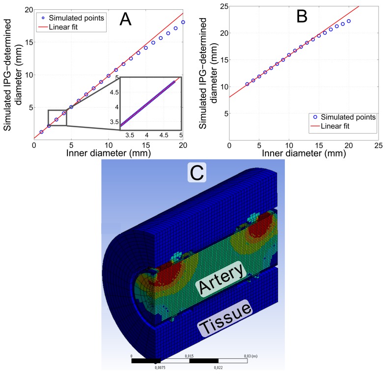
Simulation of the diameter, determined by IPG measurements using the FEM model shown in Figure 4. (A) Simulation of an extended range of the arterial diameter for an ex vivo artery. The inset magnifies the physiologically most relevant part with a correlation of r = 1.0. The slope of the linear fit is m = 0.96 and the offset c = 0.25 mm. (B) Simulation considering in vivo conditions with 20 mm of tissue around the artery. The slope of the linear fit is m = 0.78 and the offset c = 8 mm; correlation coefficient r = 0.9997. (C) The model considering in vivo conditions with additional layers of tissue.
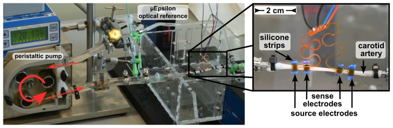
Setup of the ex vivo measurement with a carotid artery of a domestic pig in an artificial circulatory system. The IPG electrodes are mounted on the artery using flexible silicone strips.
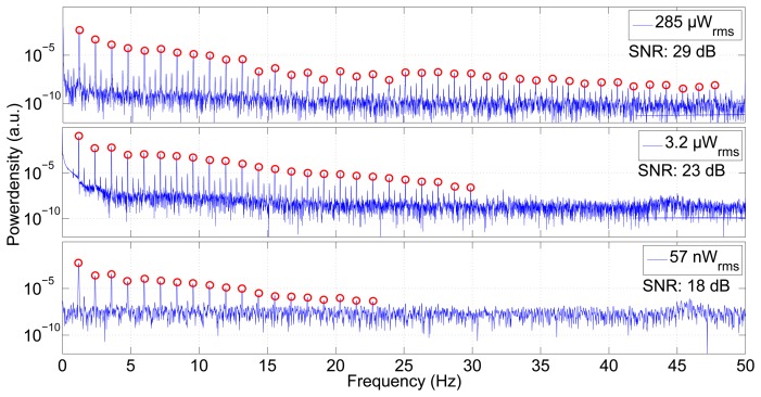
Power spectral density of the measurement shown in Figure 8. The three plots differ in the current fed into the source electrodes. Higher current and, hence, higher power produces an excellent signal-to-noise ratio, making the pumping frequency and more than 40 harmonics visible. Even a very low power of 57 nW reveals the pumping rate and 18 overtones. The signal-to-noise ratio (SNR) decreases with lower power.
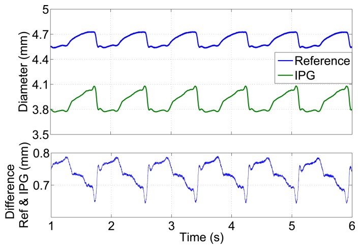
Diameter versus time for a carotid artery of a domestic pig in an ex vivo measurement in an artificial circulatory system measured by the optical μEpsilon reference and by impedance plethysmography. The lower plot shows the deviation between both plots.
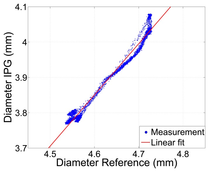
Arterial diameter determined by IPG, using Equation (2)
vs. a reference measurement of the outer diameter. Correlation coefficient r = 0.99.
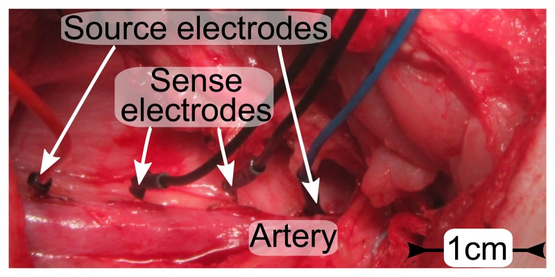
Photo of electrodes placed on the femoral artery (Ø 9 mm) of a domestic pig. The spacing is 1 cm between sense electrodes and 3 cm between source electrodes.
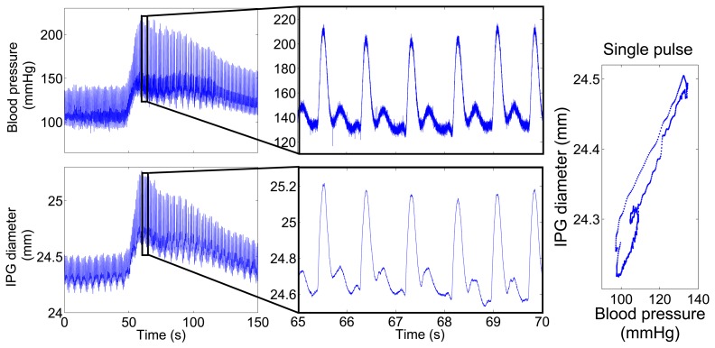
Measured blood pressure and IPG-determined diameter over time. After 50 s, the blood pressure was increased by a bolus of 50 μg noradrenaline. (Left) The complete measurement over 150 s. (Middle) Plot zoom into 5 s of the same measurement to visualize the blood pulses with a heart rate of 70/min. (Right) The plot displays blood pressure vs. IPG-signal for a single pulse.
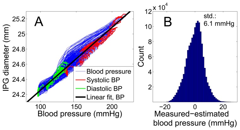
Comparison of intra-arterial blood pressure and vessel expansion measured by IPG for 200 blood pulses. (A) Direct comparison of the entire 150 s of the measurement data shown in Figure 11 with a linear fit curve, which is used for calibration. (B) The histogram shows the deviation of IPG-determined blood pressure for the same measurement, using the calibration curve from (A). The standard deviation is 6.1 mmHg.
References
-
- World Health Organization . Global Health Risk—Mortality and Burdan of Disease Attributable to Selected Major Risk. World Health Organization; Geneva, Switzerland: 2009.
-
- OBrien E., Asmar R., Beilin L., Verdecchia P. European Society of Hypertension recommendations for conventional, ambulatory and home blood pressure measurement. J. Hypertens. 2003;21:821–848. - PubMed
-
- Vij R., Peixoto A. Management of nocturnal hypertension. Expert Rev. Cardiovasc. Ther. 2009;7:607–618. - PubMed
-
- Heinen-Kammerer T., Wiosna W., Nelles S., Rychlik R. Health Technology Assessment-Bericht 30: Monitoring von Herzfunktionen mit Telemetrie. Heinen-Kammerer; Cologne, Germany: 2006.
-
- Boriani G., Diemberger I., Martignani C., Biffi M., Valzania C., Bertini M., Domenichini G., Saporito D., Ziacchi M., Branzi A. Telecardiology and Remote Monitoring of Implanted Electrical Devices: The Potential for Fresh Clinical Care Perspectives. J. Gen. Intern. Med. 2008;23:73–77. - PMC - PubMed
Publication types
MeSH terms
LinkOut - more resources
Full Text Sources
Other Literature Sources
