. 2013 Jun 1;16(6):229-241.
doi: 10.1016/j.mattod.2013.06.005.

Biomimetic electrospun nanofibrous structures for tissue engineering

Affiliations

Biomimetic electrospun nanofibrous structures for tissue engineering

Xianfeng Wang et al. Mater Today (Kidlington). .

Abstract

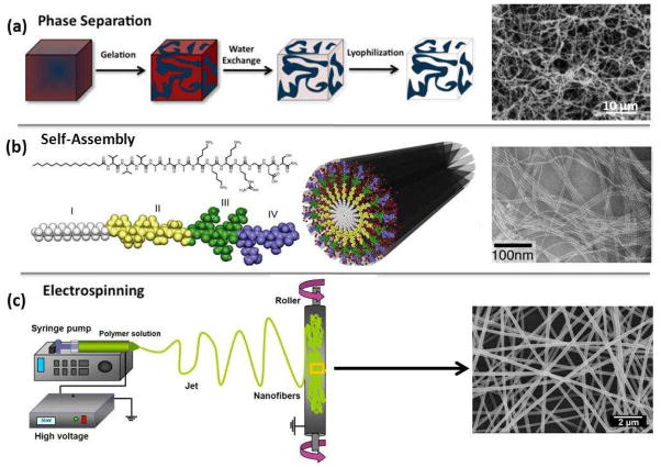
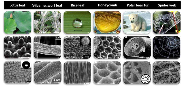
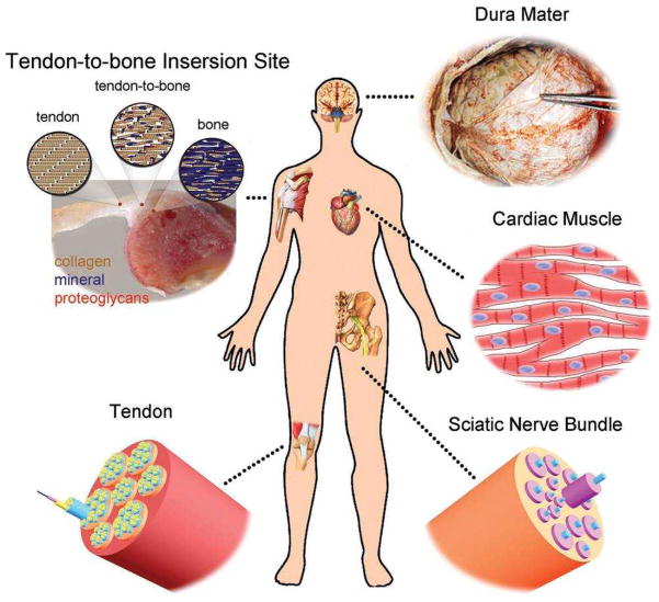
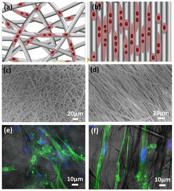
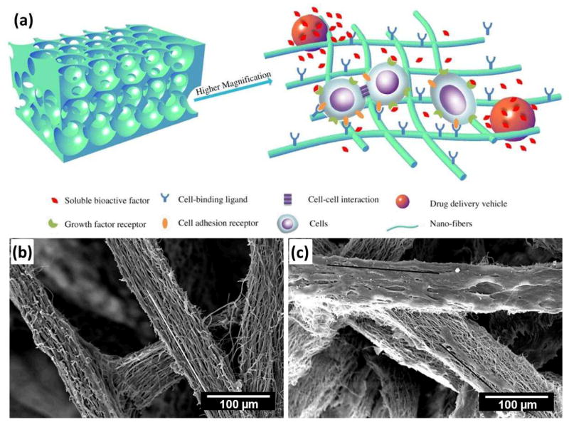
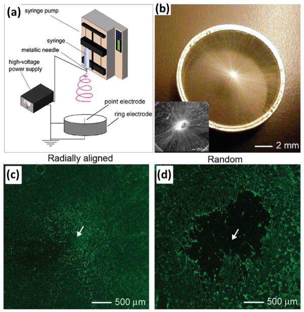
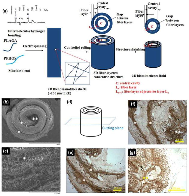
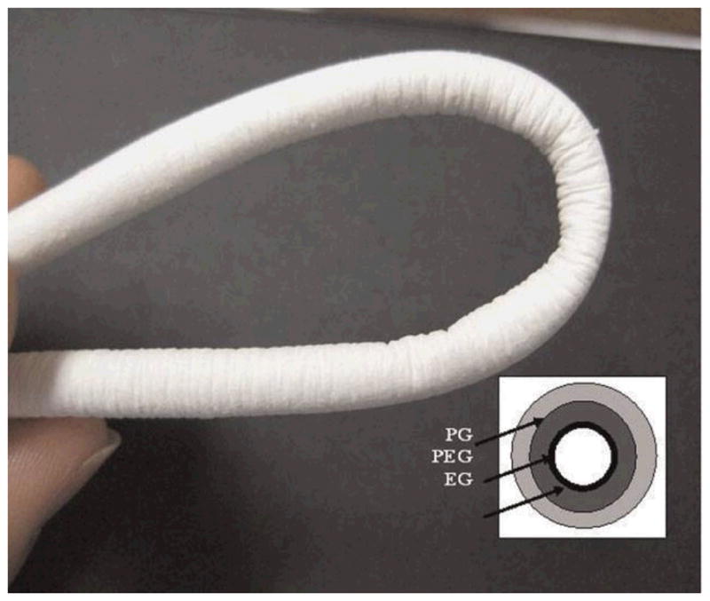
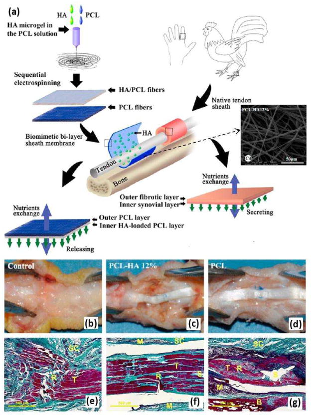
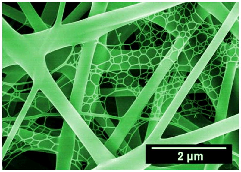
Biomimetic nanofibrous scaffolds mimicking important features of the native extracellular matrix provide a promising strategy to restore functions or achieve favorable responses for tissue regeneration. This review provides a brief overview of current state-of-the-art research designing and using biomimetic electrospun nanofibers as scaffolds for tissue engineering. It begins with a brief introduction of electrospinning and nanofibers, with a focus on issues related to the biomimetic design aspects. The review next focuses on several typical biomimetic nanofibrous structures (e.g. aligned, aligned to random, spiral, tubular, and sheath membrane) that have great potential for tissue engineering scaffolds, and describes their fabrication, advantages, and applications in tissue engineering. The review concludes with perspectives on challenges and future directions for design, fabrication, and utilization of scaffolds based on electrospun nanofibers.


Figures

Figure 1
Figure 1
Schematic of current techniques (i.e., phase separation, self-assembly, and electrospinning) to create fibrillar structures in synthetic scaffolds. (a) Reprinted with permission from. © 2012 Elsevier B.V.). (b) Reprinted with permission from. © 2011 Elsevier B.V. Scanning electron microscopy (SEM) images adapted and reprinted with permission (a) from. © 1999 WILEY-VCH Verlag GmbH & Co. and (b) from. © 2002 The National Academy of Sciences of the USA.
Figure 2
Figure 2
Biomimetic electrospun nanofibrous structures inspired from nature. In each case the first row shows a photograph of the biological feature, the second row shows the optical or SEM images of corresponding micro- and nanometer-scale structures, and the third row shows the SEM images of inspired electrospun nanofibrous structures.
Figure 3
Figure 3
Illustration of some typical examples of tissues in the human body whose regeneration would benefit from the use of nanofiber-based scaffolds that could be readily fabricated by electrospinning. (Reprinted with permission from. © 2012 WILEY-VCH Verlag GmbH & Co.)
Figure 4
Figure 4
Schematic of nanofibers with (a) random orientation and (b) alignment for the guidance of cell migration and extension. (Reprinted with permission from. © 2012 Elsevier B.V.) (c–f) SEM micrographs of PCL scaffolds for hSC culture: (c) randomly oriented and (d) aligned PCL electrospun fibers; and (e, f) their corresponding fluorescent-light images overlay of hSCs cultured on PCL scaffolds for 3 days. (Reprinted with permission from. © 2008 Elsevier B.V.)
Figure 5
Figure 5
(a) Schematic illustration of a biomimetic nanofibrous scaffold with integrated synthetic osteogenic microenvironment. The porous scaffold can not only provide a physical structure that accommodates cells and tissue formation, but also serve as an ECM-mimicking matrix to enhance cell-scaffold interactions and delivery of bioactive agents and/or stem cells in a 3D controlled manner. (Reprinted with permission from. © 2012 Elsevier B.V.) (b, c) SEM micrographs of 3D MNF scaffolds (b) without and (c) with in vitro growth of hESC-MSCs cells (white line indicates the direction of aligned nanofiber, black line indicates the direction of cell elongation). (Reprinted with permission from. © 2012 WILEY-VCH Verlag GmbH & Co.)
Figure 6
Figure 6
(a) Electrospinning setup for generating scaffolds consisting of radially aligned nanofibers. (b) Photograph of a scaffold of radially aligned nanofibers directly deposited on the ring collector. Inset of (b) shows the SEM image of the radial alignment nanofibers. (c, d) Fluorescence micrographs comparing the migration of cells when dura tissues were cultured on scaffolds of random and radially aligned nanofibers, respectively, for 4 days. The dashed circle line indicates the border of dura cells after seeding at day 0. (Reprinted with permission from. © 2010 American Chemical Society.)
Figure 7
Figure 7
(a) Schematics of 3D biomimetic scaffold design and fabrication. ECM deposition throughout 3D scaffold architecture during cell culture. (b, c) SEM images showing the morphologies of cell-seeded 3D biomimetic scaffolds after 28 days of culture: (b) Cell layers covering the scaffold; and (c) ECM deposited by the cells bridging the gaps in the concentric pattern by 28 days. Cells could migrate through 250 μm thick concentric fiber laminates from both the surfaces leading to a homogeneous ECM deposition and cellular activity throughout the biomimetic scaffold. (d–g) Immunohistochemical staining for osteopontin, a prominent component of the mineralized ECM, illustrating a homogenous ECM distribution throughout the scaffold at day 28: (d) Schematics of the select plane for immunohistochemical staining. (e, f) A robust stain for osteopontin bridging the gap between the concentric layers for the lower portion as well as upper and center portion of the 3D biomimetic scaffold. (g) Higher magnification image of the central cavity showing the robust stain for osteopontin. (*) indicates inter-lamellar space whereas (**) indicates central cavity. PLAGA: poly(lactide-co-glycolide), PPHOS: poly[(glycine ethyl glycinato)1(phenylphenoxy)1phosphazene] (Reprinted with permission from. © 2011 WILEY-VCH Verlag GmbH & Co.)
Figure 8
Figure 8
Photograph of tubular conduit of 20 cm length and 4 mm inner diameter. Inset is a schematic showing the trilayer tubular conduit (EG/PEG/PG) with spatially designed layers of elastin/gelatin (EG), PDO/elastin/gelatine (PEG), and PDO/gelatine (PG). The lumen layer is rich in protein and outer layers are rich in PDO. (Reprinted with permission from. © 2009 WILEY-VCH Verlag GmbH & Co.)
Figure 9
Figure 9
(a) After formation of HA microgel in the PCL solution, a biomimetic bilayer sheath membrane was fabricated by sequential electrospinning, producing a sheath membrane consisting of a PCL-HA fibrous membrane as the inner layer and a PCL fibrous membrane as the outer layer to imitate the synovial layer and the fibrotic layer, respectively, of native sheath. (b-d) Gross evaluation of a chicken model of flexor digitorum profundus tendon repair after 21 days. (b) Untreated control group; (c) group treated with sheath membrane with inner PCL-HA PCL layer; (d) group treated with PCL membrane. (eg) Histological assessments of the tendons repaired using each of the treatments. Masson’s trichrome staining of untreated repair site (e); repair site wrapped with sheath membrane with inner PCL-HA PCL layer (f); repair site wrapped with PCL membrane (g). Subcutaneous tissue (SC), tendon (T), sutured site (S), bone (B), and materials (M) could be detected. (Reprinted with permission from. © 2012 American Chemical Society.)
Figure 10
Figure 10
SEM image of nano-fiber/net fabricated by ESN technique comprising common electrospun nanofibers and spider-web-like nano-nets. (Reprinted with permission from. © 2010 IOP Publishing Ltd.)

References

    1. Dvir T, et al. Nat Nanotechnol. 2011;6:13. - PMC - PubMed
    1. Stevens MM, George JH. Science. 2005;310:1135. - PubMed
    1. Ma PX. Adv Drug Deliv Rev. 2008;60:184. - PMC - PubMed
    1. Li YP, et al. Angew Chem Int Edit. 2012;51:2864.
    1. Zhang XH, et al. Adv Drug Deliv Rev. 2009;61:988. - PMC - PubMed