. 2014 Aug 19;107(4):825-33.
doi: 10.1016/j.bpj.2014.06.045.

Geometry regulates traction stresses in adherent cells

Affiliations

Geometry regulates traction stresses in adherent cells

Patrick W Oakes et al. Biophys J. .

Abstract

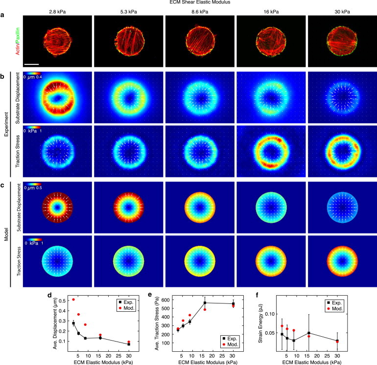
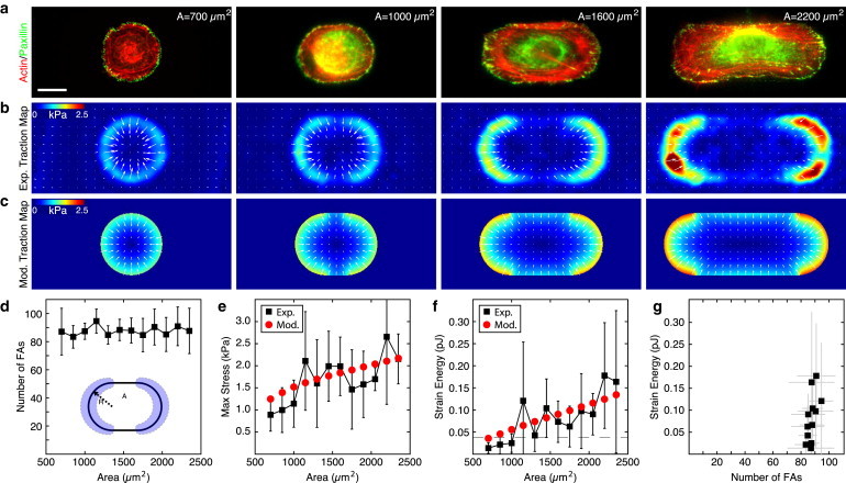
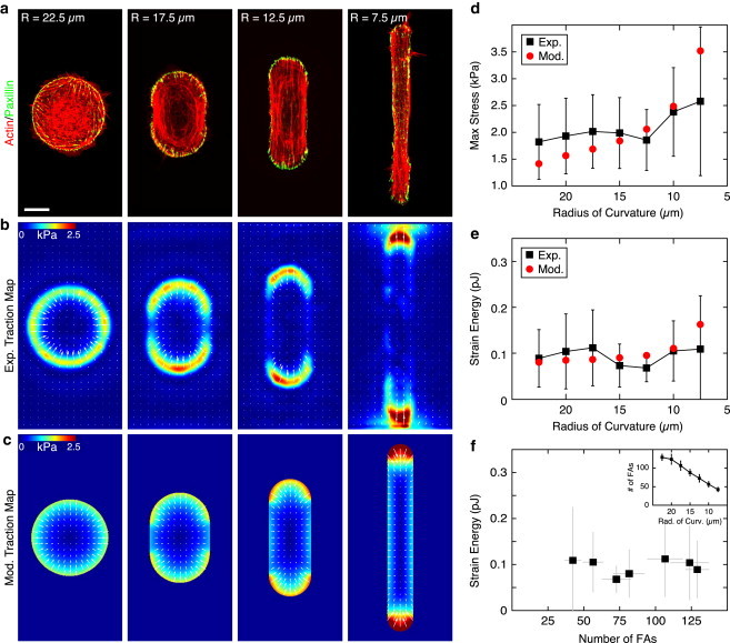
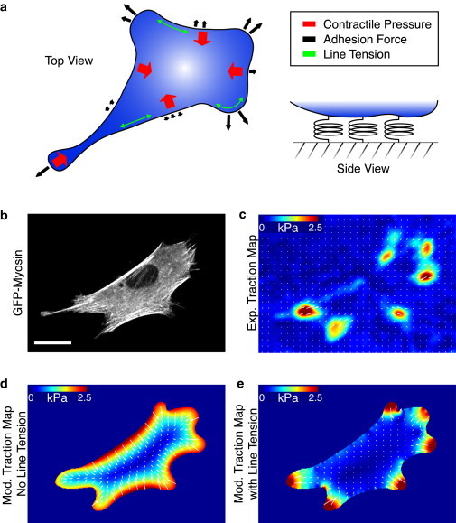
Cells generate mechanical stresses via the action of myosin motors on the actin cytoskeleton. Although the molecular origin of force generation is well understood, we currently lack an understanding of the regulation of force transmission at cellular length scales. Here, using 3T3 fibroblasts, we experimentally decouple the effects of substrate stiffness, focal adhesion density, and cell morphology to show that the total amount of work a cell does against the substrate to which it is adhered is regulated by the cell spread area alone. Surprisingly, the number of focal adhesions and the substrate stiffness have little effect on regulating the work done on the substrate by the cell. For a given spread area, the local curvature along the cell edge regulates the distribution and magnitude of traction stresses to maintain a constant strain energy. A physical model of the adherent cell as a contractile gel under a uniform boundary tension and mechanically coupled to an elastic substrate quantitatively captures the spatial distribution and magnitude of traction stresses. With a single choice of parameters, this model accurately predicts the cell's mechanical output over a wide range of cell geometries.


Figures

Figure 1
Figure 1
Strain energy is independent of substrate stiffness. (a) Representative immunofluorescence of fibroblasts plated on 800 μm2 patterns of fibronectin on gels of varying shear modulus. (Red) Actin; (green) focal adhesion protein paxillin. Scale bar is 15 μm. (b) Average experimental substrate displacement and traction stress maps for gels of each shear modulus. (c) Substrate displacement and traction stress maps produced using the model of a contractile gel with a uniform line tension on substrates of different stiffness. (d and e) Average substrate displacement and traction stress along the pattern edge, as measured experimentally (black squares) and predicted by the model (red circles). Error bars represent standard error of the mean with a minimum of 17 cells per point. (f) Mean strain energy as measured experimentally (black squares) and predicted by the model (red circles) as a function of substrate stiffness. Error bars represent standard deviation with a minimum of 17 cells per point. Model parameters: Ecell = 5.4 kPa, ν = 0.43, σa = 2.4 kPa, and fm = 0.7 nN/μm. To see this figure in color, go online.
Figure 2
Figure 2
Strain energy scales with cell size independent of number of focal adhesions. (a) Immunofluorescence images of actin (red) and the focal adhesion protein paxillin (green) in fibroblasts plated on micropatterns that increase with area and maintain a constant radius of curvature at the ends. Scale bar is 20 μm. (b) Average experimental traction force maps (n > 4 for each image). (c) Traction maps produced using the model of a contractile gel with a uniform line tension. (d) Number of focal adhesions in the regions of curvature of the pattern. Error bars represent standard deviation with a minimum of three cells per point. (Inset) Schematic indicating the radius of curvature, R, and area, A of the pattern. (Shaded) Regions used to calculate the number of focal adhesions. (e and f) Mean maximum stress and mean strain energy plotted as a function of pattern area. (Black squares) Experimental results. Error bars represent standard deviation with a minimum of four cells per point. (Red circles) Model results. Model parameters: Ecell = 5.4 kPa, ν = 0.43, σa = 2.4 kPa, and fm = 0.7 nN/μm. (Dashed line) Mean strain energy for 800 μm2 circles of different stiffness (from Fig. 1f). (g) Strain energy plotted as a function of the number of focal adhesions bearing the load. To see this figure in color, go online.
Figure 3
Figure 3
Local curvature regulates the distribution of traction stress for a constant area. (a) Immunofluorescence images of actin (red) and the focal adhesion protein paxillin (green) in fibroblasts plated on micropatterns of a constant area (1600 μm2) and changing radius of curvature. Scale bar is 15 μm. (b) Average experimental traction-force maps (n > 7 for each image). (c) Traction maps produced using the model of a contractile gel with a uniform line tension. (d and e) Mean maximum stress and mean strain energy plotted as a function of pattern area. (Black squares) Experimental results. Error bars represent standard deviation with a minimum of seven cells per point. (Red circles) Model results. Model parameters: Ecell = 5.4 kPa, ν = 0.43, σa = 2.4 kPa, and fm = 0.7 nN/μm. (f) The strain energy plotted as a function of the number of focal adhesions bearing the load. (Inset) Number of focal adhesions bearing the load plotted as a function of the radius of curvature of the pattern. Error bars represent standard deviation with a minimum of three cells per point. To see this figure in color, go online.
Figure 4
Figure 4
Model of unconstrained fibroblasts. (a) A force-balance diagram illustrating the components in the model, including an isotropic contractile pressure throughout the cell, uniform line tension along the periphery, and the adhesion force dependent on local boundary curvature. (b) A cell expressing GFP-myosin on an 8-kPa polyacrylamide substrate uniformly coated with fibronectin. Scale bar is 20 μm. (c) Experimental traction map for the cell in panel b. (d) The traction map produced by a model of a uniformly contracting gel without including a line tension, σa = 7 kPa and fm = 0. (e) The traction map produced from the model of the cell as a contractile gel with a uniform line tension, σa = 2.4 kPa and fm = 0.7 nN/μm. Other model parameters: Ecell = 5.4 kPa and ν = 0.43. To see this figure in color, go online.

Comment in

References

    1. Lecuit T., Lenne P.-F. Cell surface mechanics and the control of cell shape, tissue patterns and morphogenesis. Nat. Rev. Mol. Cell Biol. 2007;8:633–644. - PubMed
    1. Parsons J.T., Horwitz A.R., Schwartz M.A. Cell adhesion: integrating cytoskeletal dynamics and cellular tension. Nat. Rev. Mol. Cell Biol. 2010;11:633–643. - PMC - PubMed
    1. DuFort C.C., Paszek M.J., Weaver V.M. Balancing forces: architectural control of mechanotransduction. Nat. Rev. Mol. Cell Biol. 2011;12:308–319. - PMC - PubMed
    1. Hoffman B.D., Grashoff C., Schwartz M.A. Dynamic molecular processes mediate cellular mechanotransduction. Nature. 2011;475:316–323. - PMC - PubMed
    1. Gupton S.L., Waterman-Storer C.M. Spatiotemporal feedback between actomyosin and focal-adhesion systems optimizes rapid cell migration. Cell. 2006;125:1361–1374. - PubMed

Publication types