. 2005 Jan;68(1):237-270.
doi: 10.1088/0034-4885/68/1/R05.

Nucleic Acid Nanostructures: Bottom-Up Control of Geometry on the Nanoscale

Affiliations

Nucleic Acid Nanostructures: Bottom-Up Control of Geometry on the Nanoscale

Nadrian C Seeman et al. Rep Prog Phys. 2005 Jan.

Abstract

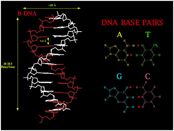
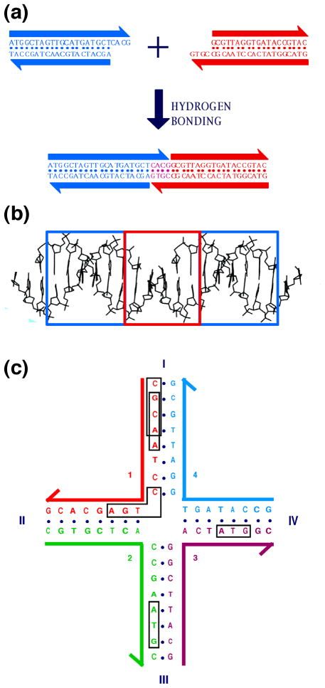
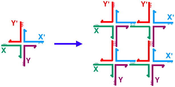
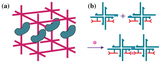
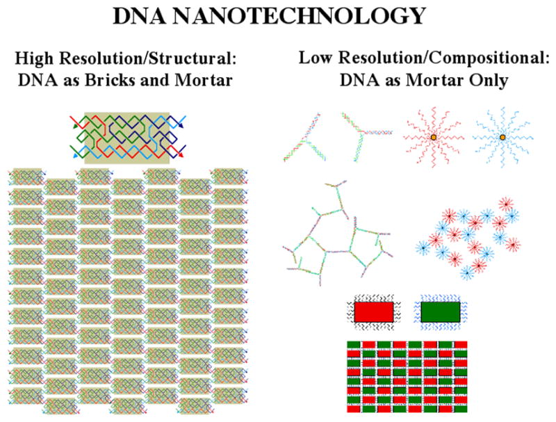
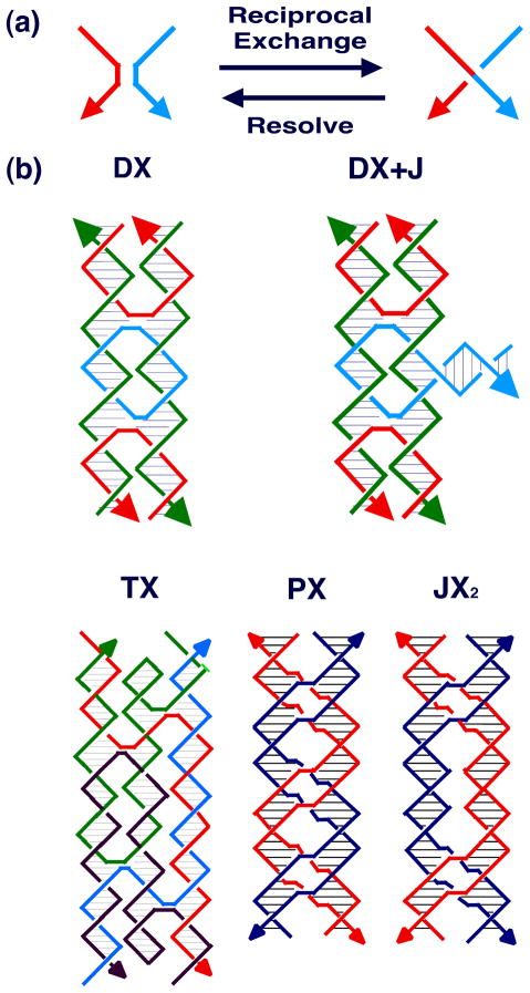
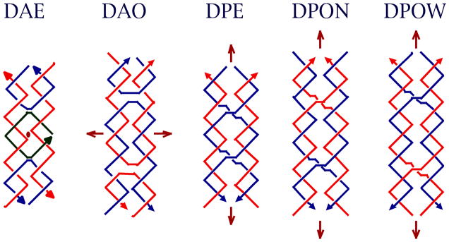
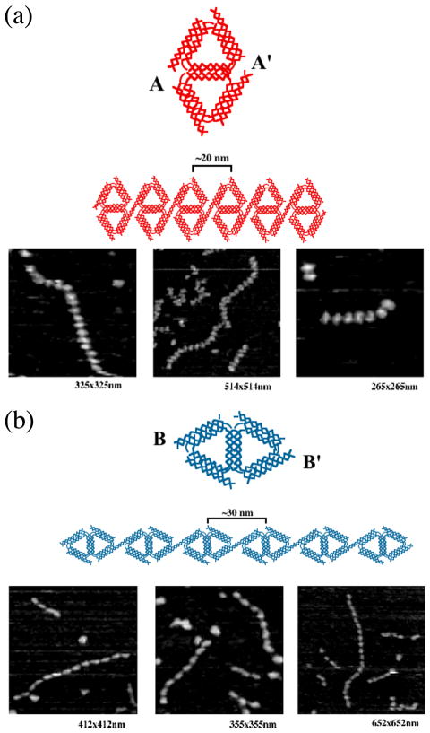
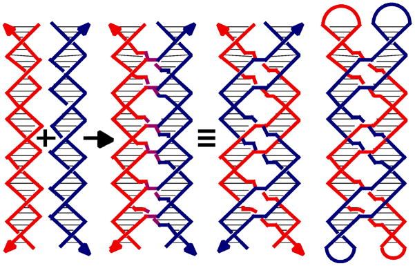
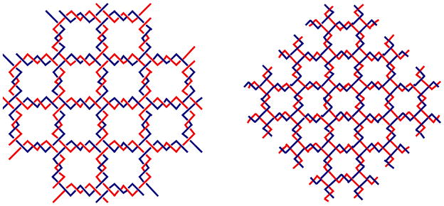
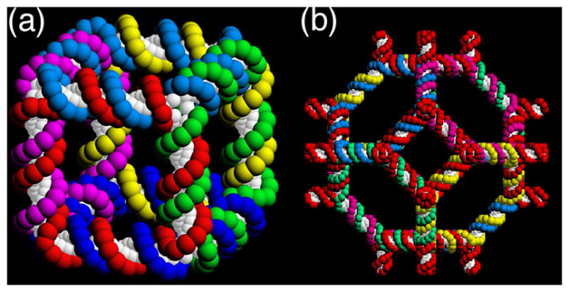
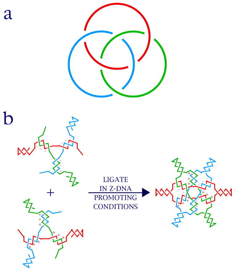
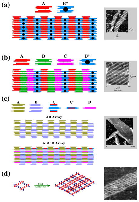
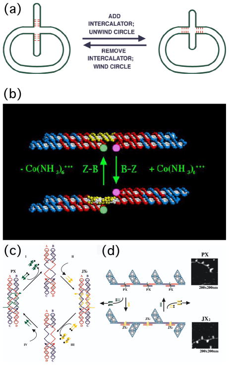
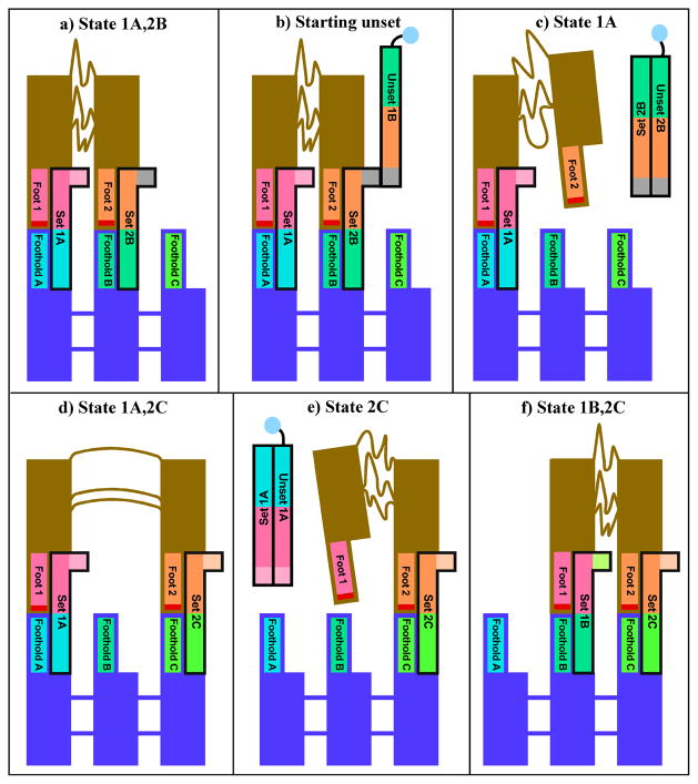
DNA may seem an unlikely molecule from which to build nanostructures, but this is not correct. The specificity of interaction that enables DNA to function so successfully as genetic material also enables its use as a smart molecule for construction on the nanoscale. The key to using DNA for this purpose is the design of stable branched molecules, which expand its ability to interact specifically with other nucleic acid molecules. The same interactions used by genetic engineers can be used to make cohesive interactions with other DNA molecules that lead to a variety of new species. Branched DNA molecules are easy to design, and the can assume a variety of structural motifs. These can be used for purposes both of specific construction, such as polyhedra, and for the assembly of topological targets. A variety of two-dimensional periodic arrays with specific patterns have been made. DNA nanomechanical devices have been built with a series of different triggers, small molecules, nucleic acid molecules and proteins. Recently, progress has been made in self-replication of DNA nano-constructs, and in the scaffolding of other species into DNA arrangements.

Keywords: Branched DNA; DNA devices; DNA periodic arrays; DNA polyhedra; DNA scaffolding; atomic force microscopy; self-assembly; unusual DNA motifs.


Figures

Figure 1
Figure 1. B-DNA
The molecular structure and dimensions of key freatures of the molecule is shown on the left. The base pairs are shown on the right, where red arrows represent hydrogen bonded interactions.
Figure 2
Figure 2. Sticky Ended Cohesion and Branched DNA
(a) Affinity in Sticky Ended Cohesion. Two double helical strands with complementary overhangs are shown. Under appropriate conditions, they will cohere in a sequence-specific fashion, and can be ligated, if desired. (b) Structure in Sticky-Ends. A portion of the crystal structure of an infinite DNA double helix formed by sticky-ended cohesion is shown. The part cohering by sticky ends is in the red box, whereas the blue boxes surround continuous DNA segments. The DNA in all three sections is B-DNA. (c) A Stable Branched Junction. There is no dyad symmetry flanking the branch point; tetramers, such as the boxed sequences CGCA and GCAA are unique, and there is no TCAG to complement the CTGA flanking the corner.
Figure 3
Figure 3. Sticky-Ended Assembly of Branched Molecules
A branched molecule is shown on the left with four sticky ends, X, complementary to X', and Y, complementary to Y'. Four of them are shown to assemble to form a quadrilateral, with further sticky ends on the outside, so that an infinite lattice could be formed by the addition of further components.
Figure 4
Figure 4. Scaffolding Applications of Structural DNA Nanotechnology
(a) Scaffolding of Biological Macromolecules for Crystallographic Purposes. A DNA box (magenta) is shown with sticky ends protruding from it. Macromolecules are organized parallel to each other within the box, rendering them amenable to crystallographic structure determination. (b) Scaffolding Nanoelectronics. Blue branched DNA junctions direct the assembly of attached nanoelectronic components (red) to form a molecular synapse stabilized by the presence of an ion.
Figure 5
Figure 5. Types of DNA Nanotechnology
High resolution/structural DNA nanotechnology is shown on the left, where DNA is both the bricks and mortar of an assembly. A TX molecule is shown assembled into a 2D array. Low resolution/compositional DNA nanotechnology is shown on the right with floppy components or applications using DNA as 'smart glue' (top). This type of DNA nanotechnology can also be used to build structures, as shown at bottom, but the resolution is not as high.
Figure 6
Figure 6. Motif Generation
(a) The Process of Reciprocal Exchange. A red strand and a blue strand exchange to form a red-blue strand and a blue-red strand. (b) Motifs used in Structural DNA Nanotechnology. Two reciprocal exchanges between strands of opposite polarity yield the DX molecule shown. The 'D' means that there are two double helices. The DX+J (a DX combined with a junction) motif, usually made with the extra helix roughly perpendicular to the plane of the other two, is made by combining a DNA hairpin and a DX molecule. The TX (indicating three fused double helices) motif results from combining the DX molecule with another double helix. The PX (standing for paranemic crossover DNA) motif is derived by performing reciprocal exchange between two helices at all possible positions where strands of the same polarity come together. The JX2 (indicating a PX with two juxtaposed backbone groups) motif is similar to the PX motif, except that reciprocal exchange is omitted at two adjacent juxtapositions.
Figure 7
Figure 7. DX Conformational Isomers
Brown arrows indicate dyad axes, and arrowheads on strands indicate 3' ends. The second character of the name indicates antiparallel (DAE and DAO), with dyad axes perpendicular to the plane of the helix axes, or parallel (DPE, DPON, DPOW), with the dyad axis coplanar with the helix axes. The third character indicates whether there is an even (DAE or DPE) number of half-turns between crossovers, or an odd number (DAO, DPON, DPOW). Odd parallel molecules are further differentiated by a fourth character, N or W, indicating whether the extra half turn is a minor (N -- narrow) groove separation or a major (W -- wide) groove separation.
Figure 8
Figure 8. Edge-Sharing Cohesion
(a) A 1D array of Edge-Sharing Diamonds Joined in their Short Direction. A schematic of the molecule is shown at top in red, as is a schematic of the 1D array. Three AFM views of arrays are shown beneath the schematics. (b) A 1D array of Edge-Sharing Diamonds Joined in their Long Direction. The same conventions apply as in (a), except that the schematics are in blue. Note the difference in the 1D arrays.
Figure 9
Figure 9. Paranemic Cohesion
The origin of the motif is shown at the left, where a red and a blue double helix exchange strands at every point, that they come in contact, to produce purple crossovers. The covalent strand structure is shown to the right of the identity sign, where a red and a blue double helix are seen to inter-wrap. The paranemic relationship of the inter-wrapped helices is emphasized on the right where the blue and red helices are capped in hairpin loops.
Figure 10
Figure 10. Impact of Topology in Branched Networks
Both arrays are extended versions of the array illustrated in Figure 3, but the twisting of the helices is indicated. The array on the left contains an even number of half-turns between vertices, leading to an array that consists of molecular chain main, red circles linked to blue circles. The array on the right contains an odd number of half-turns between vertices, leading to an interwoven structure, blue chains going lower right to upper left, and red chains going lower left to upper right.
Figure 11
Figure 11. Polyhedral Catenanes
(a) A Stick Cube and (b) a Stick Truncated Octahedron. The drawings show that each edge of the two figures contains two turns of double helical DNA. There are two turns of DNA between the vertices of each polyhedron, making them, respectively, a hexacatenane and a 14-catenane.
Figure 12
Figure 12. An Irregular Graph
The graph shown has explicit edges (E1–E8) as well as junctions (V1-V5). The sites of the sticky ends are indicated by patches of green. Restriction sites are indicated by the names of the restriction enzymes, biotin groups are labeled as 'B' and radioactive labeling sites are shown by asterisks. Note that this is a knot, not a catenane.
Figure 13
Figure 13. The Relationship Between Knots and Catenanes
At the upper left is a 51 knot with an arbitrary polarity. In the transition to the upper right, a node is destroyed by cutting both strands and rejoining them, while maintaining local polarity; a catenane results. The catenane is repeated on the lower left. Performing the same operation on a different node converts the catenane to a knot.
Figure 14
Figure 14. The Relationship of Nodes to DNA Half-Turns
The simplest knot, 31 is drawn with red strands and arbitrary polarity. Blue boxes are drawn about its nodes, and the strands that make the nodes serve as the diagonals of the boxes; they divide the boxes into four regions, two between parallel strands and two between antiparallel strands. Drawing a half-turn of DNA (about 6 nucleotide pairs) between the antiparallel strands effects the transition from strand topology to nucleic acid structure.
Figure 15
Figure 15. B-DNA and Z-DNA
The two forms of DNA are cartooned here. B-DNA has a simple helical structure and is right-handed, leading to negative nodes. Z-DNA is a helix with a zigzag backbone resulting from a dimer being the helical repeat unit. It is left-handed, leading to positive nodes.
Figure 16
Figure 16. Synthesis of Four Topologies from a Single Strand of DNA
X and X' represent a turn of DNA and its complement, as do Y and Y'. Both have a Z-forming propensity, but that of Y-Y' is higher. As the Z-forming nature of the solution increase, the main ligation product changes from a circle (very low ionic strength), to a trefoil knot with negative nodes (both turns B-DNA), to a figure-8 knot (the Y turn is Z-DNA), to a trefoil knot with positive nodes (both turns are Z-DNA).
Figure 17
Figure 17. Borromean Rings
(a) The Topology of Borromean Rings. Note that cleaving any ring leaves the other two rings unlinked; the key is that the nodes on the inside are of a different sign from those on the outside. (b) Forming Borromean Rings from DNA. A 3-arm DNA branched junction made of B-DNA (top) is linked to a 3-arm junction made of Z-DNA (bottom) through hairpins at the equator of the product molecule.
Figure 18
Figure 18. DNA Arrays
(a) Two DX Molecules Tile the Plane. A conventional DX molecule, A, and a DX+J molecule, B*, are seen to tile the plane. The extra domain on B* leads to stripes. The molecules are 4 x 16 nm in this projection, so the stripes are ~32 nm apart, as seen in the AFM image at the right. (b) Four DX Molecules Tile the Plane. This arrangement is similar to (a), but there is only one DX+J molecule, D*, so the stripes are separated by ~64 nm, as seen on the right. (c) A TX Array. Two TX tiles, A and B are connected by complementarity between their first and third double helical domains, resulting in spaces between the tiles. D is a linear duplex that fits in the yellow rows, and C is a TX re-phased by three nucleotide pairs; it fits into the gray rows and extends helices beyond the AB plane in both directions, as shown in the micrograph at the right. (d) A DNA Parallelogram Array. Four Holliday junction analogs form a parallelogram that is extended to produce a periodic array. The sizes of the cavities in the array may be tuned. Those in the array the right are ~13 nm x ~20 nm.
Figure 19
Figure 19. DNA Devices
(a) A Mobile Control Device. The cruciform structure on the left contains four mobile base pairs at its base. Addition of an intercalator (ethidium) unwinds the circle, moving them into it. Removal of the ethidium reverses the action of the device. (b) A DNA Nanomechanical Device Based on the B-Z Transition. The device consists of two DX molecules connected by a shaft containing 20 nucleotide pairs (yellow) capable of undergoing the B-Z transition. Under B conditions the short domains are on the same side of the shaft, but under Z-conditions (added Co(NH3)63=) they are on opposite sides of the shaft. The pink and green FRET pair are used to monitor this change. (c) The Machine Cycle of a PX-JX2 Device. Starting with the PX device on the left, the green strands are removed by their complements (Process I) to leave an unstructured frame. The addition of the yellow strands (process II) converts the frame to the JX2 structure, in which the top and bottom domains are rotated a half turn relative to their arrangement in the PX conformation. Processes III and IV reverse this process to return to the PX structure. (d) AFM Demonstration of the Operation of the Device. A series of DNA trapezoids are connected by devices. In the PX state, the trapezoids are in a parallel arrangement, but when the system is converted to the JX2 state, they are in a zigzag arrangement.
Figure 20
Figure 20. A DNA-Based Walker Walking on a Sidewalk
The states through which the system passes sequentially are shown in the panels of the drawing. Matching colors indicate complementary sequences between strands. The red section at the end of each foot indicates psoralen, which is crosslinked for analysis. (a) Initial State of the Walker Feet 1 and 2 are attached to the sidewalk by hydrogen-bonded strands. (b) and (c) Removal of the Connection of Foot 2. The Unset complex is removed from solution via a biotin group (depicted as a blue circle) attached to the unset strand. (d) Re-Attachment of Foot 2 at a New Position. (e) Release of Foot 1. (f) Re-Attachment of Foot 1 at a New Position. At this point the device has moved a complete step.
Figure 21
Figure 21. A Two-Dimensional Array Capable of Changing Cavity Dimensions
(a) Strand Diagram of the Tiles and Their Incorporation into Arrays. The red and purple set strands correspond to a contracted state, while the blue and green strands correspond to the expanded state. (b) AFM Images Illustrating the Transition. The 'before' (left), 'transition' (center) and 'after' (right) states of the array are illustrated in both directions. Reproduced with permission.
Figure 22
Figure 22. The Action of a Nanomechanical Device Working Against a Load
Double-helical DNA is shown as rectangular boxes. Triple crossover motifs (TX) are shown as three fused rectangular boxes. The upper domain connects the two TX motifs with the binding site for IHF. IHF is shown as a green ellipse, and in the lower panel its binding distorts the connecting shaft. In the upper panel the lower TX domains are held together by a sticky end. In the lower panel, these are disrupted by the binding. By changing the strength of the sticky end, the amount of work the protein can do upon binding is estimated.
Figure 23
Figure 23. An Octahedron Consisting of One Long and Five Short DNA Strands
(a) Strand Diagram of the ‘Branched Tree’ Structure. The structure consists of DX struts (double helical regions with light blue central strands), four-arm junction joints (labeled I-VI) and half-PX domains (complementary domains labeled with the same colors) destined to fold into struts. (b) 3-Dimensional Representation of the Folded Octahedron. The drawing shows the crossovers in the DX molecules as two light blue dots between cylinders and the PX associations as a series of colored dots between cylinders. (c) Electron Microscopic Images. Raw EM data are shown at top and maps onto projected octahedral symmetry of the folded octahedron are shown at the bottom. (d) Views of the 3-Dimensional Electron Density Model Based on EM Data. Reproduced with permission.
Figure 24
Figure 24. Wang Tiles and their Relationship to Branched Junctions
The upper left corner illustrates 16 Wang tiles of various types. The bottom shows a mosaic formed from them using the rule that all edges in the mosaic are flanked by the same color; this mosaic assembly that performs the calculation of adding 5 to 9 to get 14. The upper right is a color coded branched junction that, when compared to the enlarged tile at the center shows the relationship between Wang tiles and branched junctions with particular sticky ends.

References

    1. Seeman NC. Nucleic acid junctions and lattices. J Theor Biol. 1982;99:237–247. - PubMed
    1. Cohen SN, Chang ACY, Boyer HW, Helling RB. Construction of biologically functional bacterial plasmids in vitro. Proc Nat Acad Sci (USA) 1973;70:3240–3244. - PMC - PubMed
    1. Qiu H, Dewan JC, Seeman NC. A DNA decamer with a sticky end: The crystal structure of d-CGACGATCGT. J Mol Biol. 1997;267:881–898. - PubMed
    1. Seeman NC. At the crossroads of chemistry, biology and materials: structural DNA nanotechnology. Chem & Biol. 2003;10:1151–1159. - PubMed
    1. Holliday R. A mechanism for gene conversion in fungi. Genet Res. 1964;5:282–304. - PubMed