. 2014 Sep 9;111(36):12980-5.
doi: 10.1073/pnas.1408705111. Epub 2014 Aug 25.

Noncontact orientation of objects in three-dimensional space using magnetic levitation

Affiliations

Noncontact orientation of objects in three-dimensional space using magnetic levitation

Anand Bala Subramaniam et al. Proc Natl Acad Sci U S A. .

Abstract

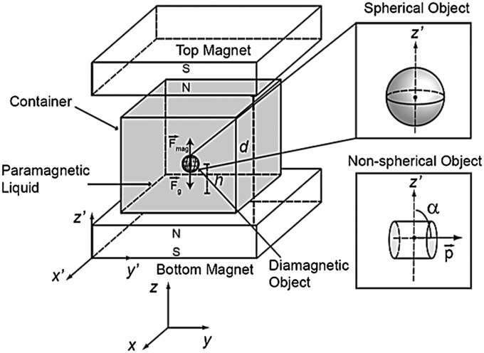
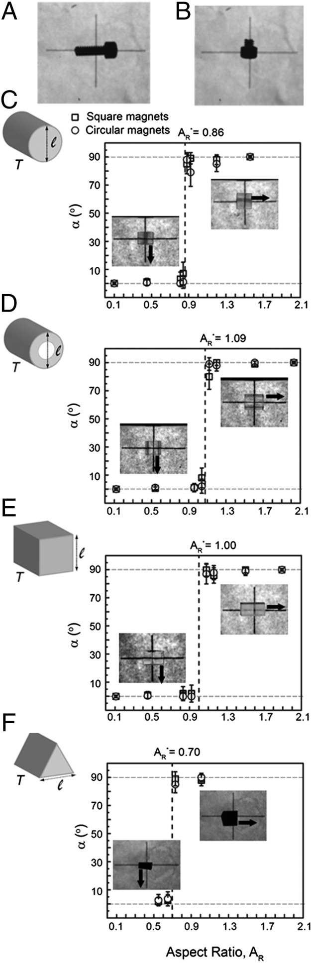
This paper describes several noncontact methods of orienting objects in 3D space using Magnetic Levitation (MagLev). The methods use two permanent magnets arranged coaxially with like poles facing and a container containing a paramagnetic liquid in which the objects are suspended. Absent external forcing, objects levitating in the device adopt predictable static orientations; the orientation depends on the shape and distribution of mass within the objects. The orientation of objects of uniform density in the MagLev device shows a sharp geometry-dependent transition: an analytical theory rationalizes this transition and predicts the orientation of objects in the MagLev device. Manipulation of the orientation of the levitating objects in space is achieved in two ways: (i) by rotating and/or translating the MagLev device while the objects are suspended in the paramagnetic solution between the magnets; (ii) by moving a small external magnet close to the levitating objects while keeping the device stationary. Unlike mechanical agitation or robotic selection, orienting using MagLev is possible for objects having a range of different physical characteristics (e.g., different shapes, sizes, and mechanical properties from hard polymers to gels and fluids). MagLev thus has the potential to be useful for sorting and positioning components in 3D space, orienting objects for assembly, constructing noncontact devices, and assembling objects composed of soft materials such as hydrogels, elastomers, and jammed granular media.

Keywords: colloidosomes; equilibrium; magneto-Archimedes levitation; self-assembly; soft robot.


Conflict of interest statement

The authors declare no conflict of interest.

Figures

Fig. 1.
Fig. 1.
Scheme describing MagLev. Two permanent magnets with like poles facing are arranged coaxially a distance d apart (the MagLev device). The laboratory fixed axes are x, y, and z, and the axes fixed on the MagLev device are x′, y′, and z′. A diamagnetic object (shown as a sphere) in a container containing paramagnetic liquid (dark gray) experiences a gravitational force Fg and a magnetic force Fmag when placed in the MagLev device. The schematic depicts the direction of the forces for an object of a higher density than the paramagnetic liquid. The direction of the vectors will be opposite for an object that is less dense than the liquid. When the two forces are in balance, the object levitates at a levitation height h. (Inset) A homogeneous spherical object has no unique plane of symmetry. To classify the orientation of nonspherical objects in the MagLev device (a cylinder is depicted here as an example), we define a unit vector p (direction vector), taken typically to be along the long axis of the object. The angle subtended by p and the z′ axis (magnetic field axis) is α. (See SI Appendix.)
Fig. 2.
Fig. 2.
Equilibrium orientations of nonspherical objects in MagLev. (A and B) A Nylon screw orients differently when the length of the shaft was reduced from 9.5 to 2.5 mm. (CF) Plots of the orientation of the objects (angle α) versus their aspect ratios AR = T/l (schematic). Each data point is an average of seven replicate objects. The error bars represent the SD. The x-error bars are smaller than the data point. The dashed vertical line is the value of the critical aspect ratio AR*, predicted by theory. (Insets) Representative images of objects levitating in the MagLev device in each plot. The black arrow indicates the direction of p. The cross in the background is for reference, and the horizontal line in the cross measured 30 mm.
Fig. 3.
Fig. 3.
Energy and orientation of objects in MagLev. (A) Plot of the potential energy as a function of α (the angle that p makes with respect to the z′ axis) (Eq. 2). R is the ratio of the second moment of area of the object. For R < 1, continuous black line, the two (degenerate) minima in potential energy occur at α = 90° and 270o. For R > 1, dashed and dotted black line, the two (degenerate) minima in potential energy occur at α = 0° and 180°. When R approaches 1, the linear theory predicts a flat energy landscape. The schematic at the top of the plot shows the orientation of the object with respect to z′. (B) Plot of α versus R for the experimental objects in Fig. 2. All of the data collapse onto a master curve with the transition in orientation at R = 1.
Fig. 4.
Fig. 4.
Controlling the orientation of a levitating object in laboratory space by rotating the MagLev device. (A) Schematic of the experimental setup. θ is the angle that the z′ axis makes relative to the z axis. (B) Experimental images taken along the y–z plane of a Nylon screw (8.5 mm in length) in the MagLev. We kept the cross in the background fixed relative to the laboratory. The screw tracks the position of the magnets, rotating a full 360° with respect to the laboratory frame of reference. The white double-headed arrows indicate the orientation of the axis of the magnetic field gradient. (C) Similar rotations caused the screw to translate and contact the wall of the container when the density of the screw was greater than the density of the solution. Further rotations caused the screw to flip orientation. For scale, the horizontal line in the cross is 30 mm.
Fig. 5.
Fig. 5.
Manipulating the orientation of an object in the x′–y′ plane of a MagLev device with an external magnet. (A) Schematic of the experimental setup. Due to the cylindrical symmetry of the magnetic field, the long axis of the screw does not have a preferred orientation in the x′–y′ plane. The image in B shows one of the orientations the screw adopts when placed in the device. (C) We moved an external magnet close to the screw to align the screw head along the red lines of the pattern. The brown square indicates the approximate position of the external magnet. Scale bar, 5 mm. Also see Fig. S5 for images taken along the z′–y′ plane of a screw being manipulated with external magnets.
Fig. 6.
Fig. 6.
Manipulation of soft, sticky, and easily deformable objects. (A) Photographs along the x′–y′ plane showing control of the orientation of a poly(N-isopropylacrylamide) hydrogel using external magnets. We used the same experimental setup as in Fig. 4. The sharp end of the hydrogel was made to point in the four principal axes of the cross pattern. The brown square indicates the approximate position of the external magnet. The hydrogel levitated stably in each position after we withdrew the external magnet. (B) Images along the z′–y′ plane of a soft-gripper component made out of EcoFlex 0030. The orientation of the gripping face was changed with respect to the laboratory frame of reference by rotating the magnets. The black double-headed arrows indicate the orientation of the axis of the magnetic field gradient, and θ is the angle of rotation of the magnets with respect to the z axis. (C) Schematic and picture of an armored droplet. The droplet adopts a stable peanut shape due to the jamming of the polystyrene particles on its interface. (D) We controlled the orientation of the armored droplet with respect to the cross pattern by using an external magnet. The manipulation of the position of the object with MagLev did not deform this soft solid. Scale bars: (A) 5 mm, (B) the horizontal line of the cross is 30 mm, (C) 2 mm, and (D) 5 mm.

References

    1. Horn BKP, Ikeuchi K. The mechanical manipulation of randomly oriented parts. Sci Am. 1984;251(2):100–111.
    1. Cappelleri DJ, Cheng P, Fink J, Gavrea B, Kumar V. Automated assembly for mesoscale parts. IEEE Trans Autom Sci Eng. 2011;8(3):598–613.
    1. Schraft RD, Ledermann T. Intelligent picking of chaotically stored objects. Assem. Autom. 2003;23(1):38–42.
    1. Shea K, Ertelt C, Gmeiner T, Ameri F. Design-to-fabrication automation for the cognitive machine shop. Adv Eng Inform. 2010;24(3):251–268.
    1. Fusco S, et al. An integrated microrobotic platform for on-demand, targeted therapeutic interventions. Adv Mater. 2014;26(6):952–957. - PubMed

Publication types