

Development of an air pneumatic suspension system for transtibial prostheses
- PMID: 25207872
- PMCID: PMC4208197
- DOI: 10.3390/s140916754
Development of an air pneumatic suspension system for transtibial prostheses
Abstract
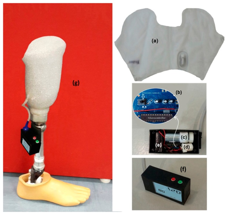
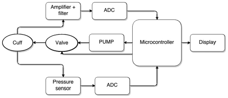
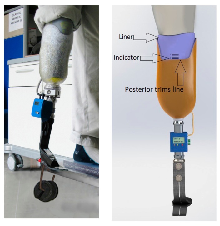
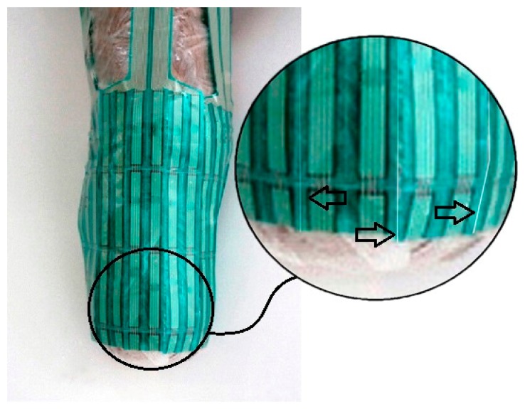
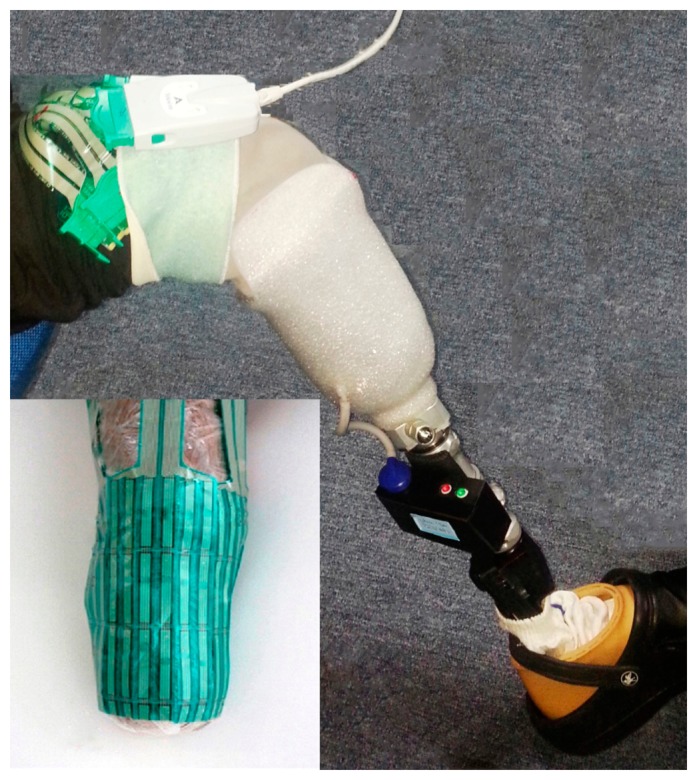
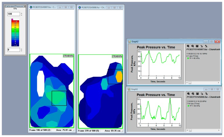
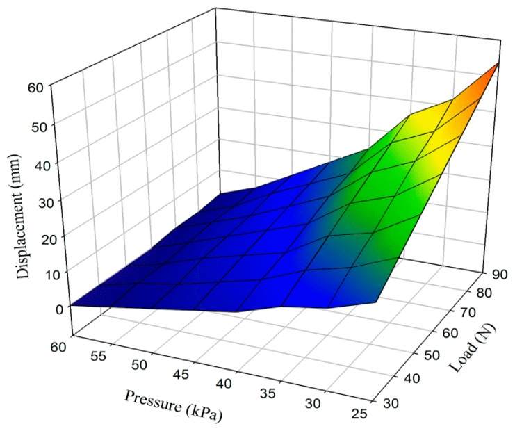
The suspension system and socket fitting of artificial limbs have major roles and vital effects on the comfort, mobility, and satisfaction of amputees. This paper introduces a new pneumatic suspension system that overcomes the drawbacks of current suspension systems in donning and doffing, change in volume during daily activities, and pressure distribution in the socket-stump interface. An air pneumatic suspension system (APSS) for total-contact sockets was designed and developed. Pistoning and pressure distribution in the socket-stump interface were tested for the new APSS. More than 95% of the area between each prosthetic socket and liner was measured using a Tekscan F-Scan pressure measurement which has developed matrix-based pressure sensing systems. The variance in pressure around the stump was 8.76 kPa. APSS exhibits less pressure concentration around the stump, improved pressure distribution, easy donning and doffing, adjustability to remain fitted to the socket during daily activities, and more adaptability to the changes in stump volume. The volume changes were adjusted by utility of air pressure sensor. The vertical displacement point and reliability of suspension were assessed using a photographic method. The optimum pressure in every level of loading weight was 55 kPa, and the maximum displacement was 6 mm when 90 N of weight was loaded.
Figures
References
-
- Kristinsson O. The iceross concept: A discussion of a philosophy. Prosthet. Orthot. Int. 1993;17:49–55. - PubMed
-
- Klute G.K., Glaister B.C., Berge J.S. Prosthetic liners for lower limb amputees: A review of the literature. Prosthet. Orthot. Int. 2010;34:146–153. - PubMed
-
- Baars E.C.T., Geertzen J.H.B. Literature review of the possible advantages of silicon liner socket use in trans-tibial prostheses. Prosthet. Orthot. Int. 2005;29:27–37. - PubMed
-
- Isozaki K., Hosoda M., Masuda T., Morita S. Cad/cam evaluation of the fit of trans-tibial sockets for trans-tibial amputation stumps. J. Med. Dent. Sci. 2006;53:51–56. - PubMed
-
- Tanner J., Berke G. Radiographic comparison of vertical tibial translation using two types of suspensions on a trans-tibial prosthesis: A case study. Prosthet. Orthot. Int. 2001;13:14–16.
Publication types
MeSH terms
LinkOut - more resources
Full Text Sources
Other Literature Sources
Medical
