. 2014 Sep-Oct;34(5):1344-62.
doi: 10.1148/rg.345140054.

Percutaneous tumor ablation tools: microwave, radiofrequency, or cryoablation--what should you use and why?

Affiliations

Percutaneous tumor ablation tools: microwave, radiofrequency, or cryoablation--what should you use and why?

J Louis Hinshaw et al. Radiographics. 2014 Sep-Oct.

Abstract

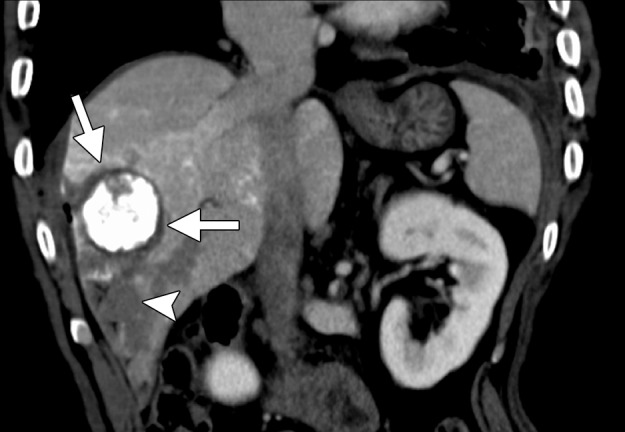
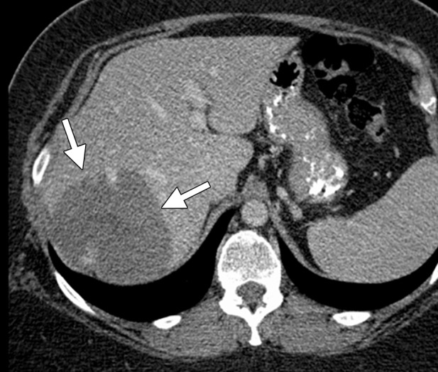
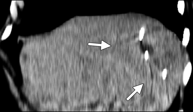
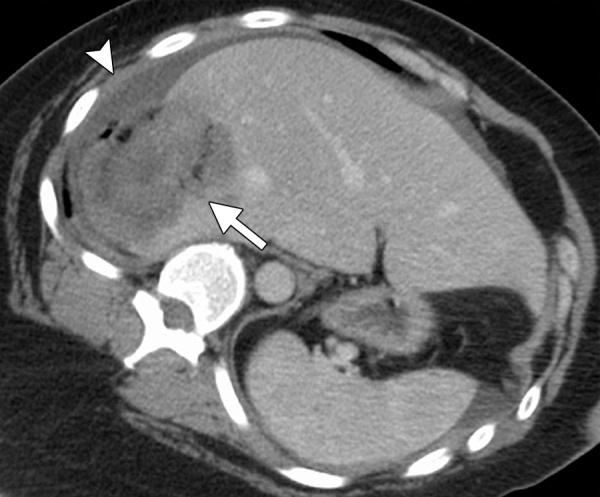
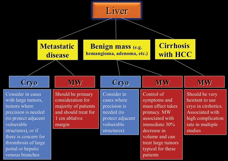
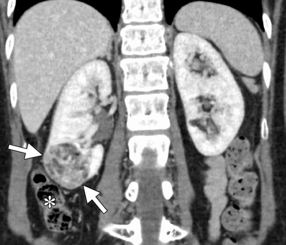
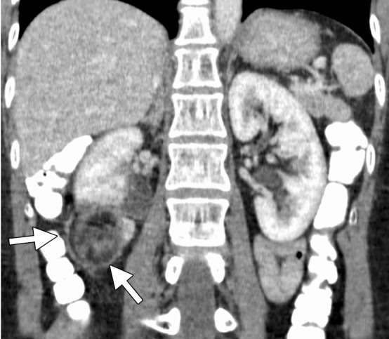
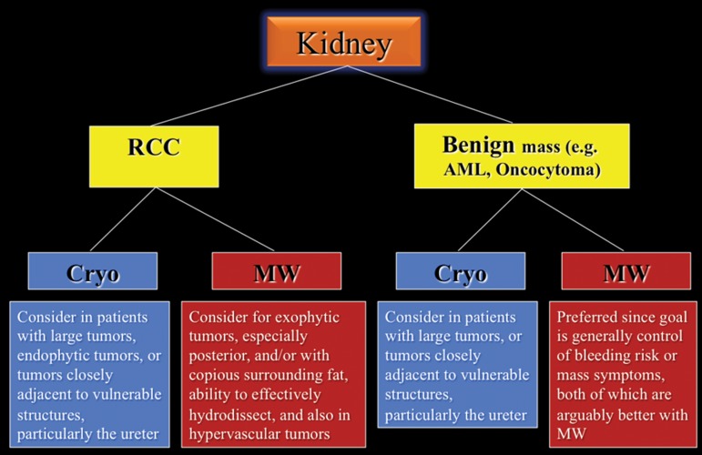
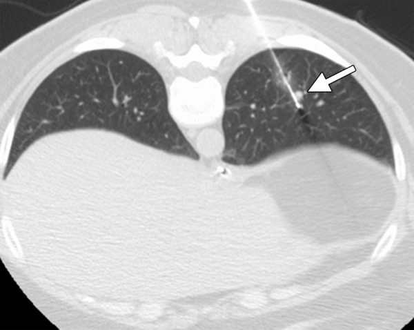
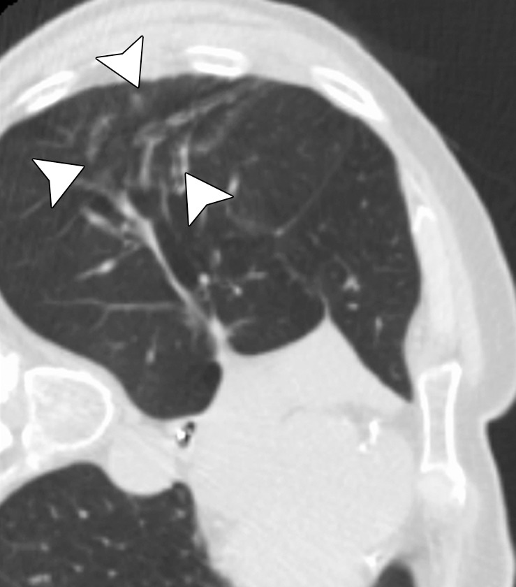
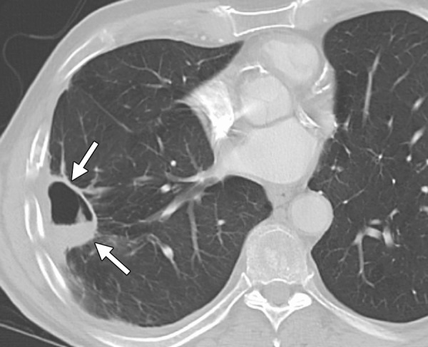
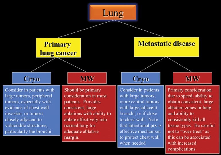
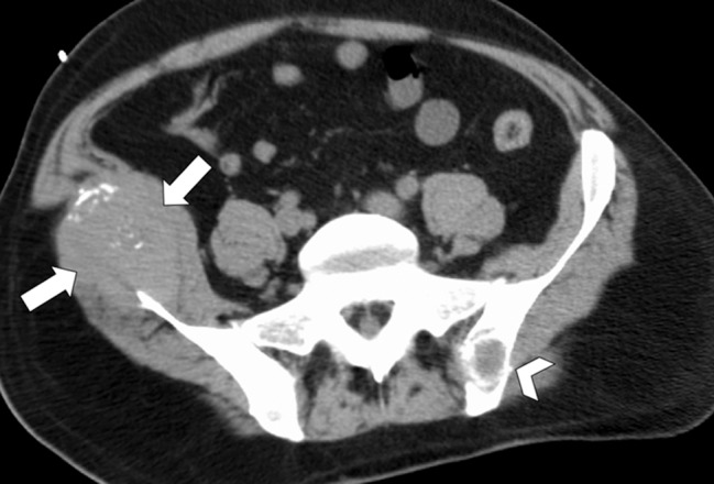
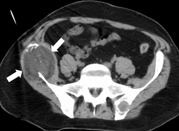
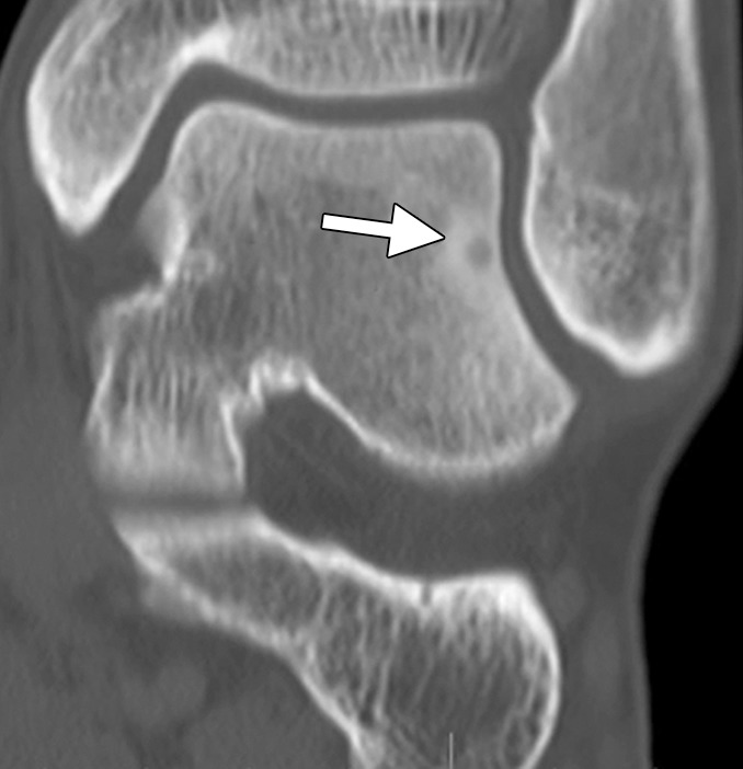
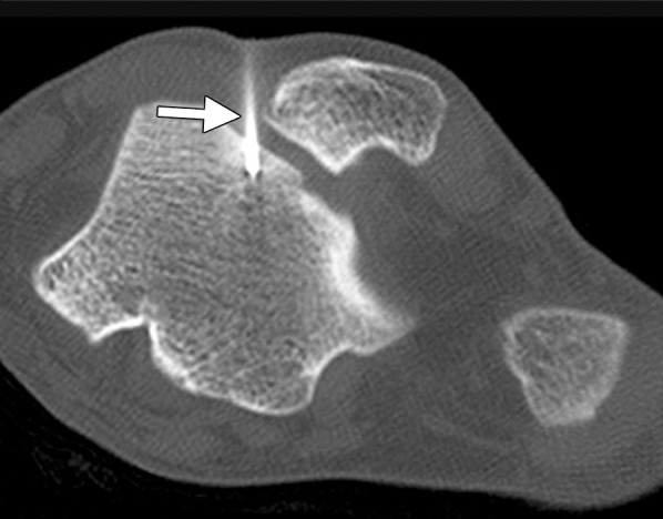
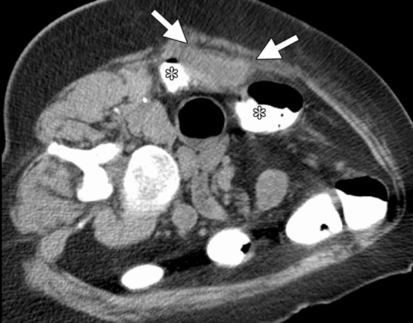
Image-guided thermal ablation is an evolving and growing treatment option for patients with malignant disease of multiple organ systems. Treatment indications have been expanding to include benign tumors as well. Specifically, the most prevalent indications to date have been in the liver (primary and metastatic disease, as well as benign tumors such as hemangiomas and adenomas), kidney (primarily renal cell carcinoma, but also benign tumors such as angiomyolipomas and oncocytomas), lung (primary and metastatic disease), and soft tissue and/or bone (primarily metastatic disease and osteoid osteomas). Each organ system has different underlying tissue characteristics, which can have profound effects on the resulting thermal changes and ablation zone. Understanding these issues is important for optimizing clinical results. In addition, thermal ablation technology has evolved rapidly during the past several decades, with substantial technical and procedural improvements that can help improve clinical outcomes and safety profiles. Staying up to date on these developments is challenging but critical because the physical properties underlying the different ablation modalities and the appropriate use of adjuncts will have a tremendous effect on treatment results. Ultimately, combining an understanding of the physical properties of the ablation modalities with an understanding of the thermal kinetics in tissue and using the most appropriate ablation modality for each patient are key to optimizing clinical outcomes. Suggested algorithms are described that will help physicians choose among the various ablation modalities for individual patients.


Figures

Figure 1
Figure 1
Graph shows the comparison of temperatures obtained with a third-generation microwave ablation system versus a similar RF ablation system. Microwave energy produces faster and hotter ablation zones than does RF current.
Figure 2
Figure 2
Diagram compares the electromagnetic fields induced by three different microwave ablation antenna designs. The differences in electromagnetic fields directly affect the size and shape of the resulting ablation zone. (Scale is in watts per kilogram.)
Figure 3a
Figure 3a
Computed tomographic (CT) images in a 77-year-old man with cirrhosis and a 2.6-cm hepatocellular carcinoma (HCC) in the right hepatic lobe. The HCC was targeted for microwave ablation with a single, specially designed “precision” 17-gauge gas-cooled antenna at 65 W for 7.5 minutes. The resulting ablation zone (arrows) shown on axial (a) and coronal (b) contrast material–enhanced postablation CT images is round and measures approximately 3.4 cm in all dimensions. Microwave ablation allowed destruction of the HCC with minimal associated damage to the hepatic parenchyma. Note the artificial ascites used to protect the diaphragm (arrowhead in b).
Figure 3b
Figure 3b
Computed tomographic (CT) images in a 77-year-old man with cirrhosis and a 2.6-cm hepatocellular carcinoma (HCC) in the right hepatic lobe. The HCC was targeted for microwave ablation with a single, specially designed “precision” 17-gauge gas-cooled antenna at 65 W for 7.5 minutes. The resulting ablation zone (arrows) shown on axial (a) and coronal (b) contrast material–enhanced postablation CT images is round and measures approximately 3.4 cm in all dimensions. Microwave ablation allowed destruction of the HCC with minimal associated damage to the hepatic parenchyma. Note the artificial ascites used to protect the diaphragm (arrowhead in b).
Figure 4a
Figure 4a
CT images in a 64-year-old male patient with cirrhosis and HCC. (a) Axial arterial phase biphasic CT image shows a 1.8-cm HCC in the right hepatic lobe (arrows). This was targeted for microwave ablation with a single 17-gauge gas-cooled antenna. A 3-minute ablation was performed at 90 W. (b) Axial nonenhanced CT image obtained during ablation shows that the mass has essentially been replaced by gas (arrow). (c) Axial CT image obtained immediately after ablation shows a 3.0 × 2.8-cm ablation zone (arrows), with complete ablation of the tumor and only the expected benign periablational enhancement (arrowhead). The high attenuation seen centrally in the ablation zone is desiccated dense tissue, which is more prominent with microwave ablation than with RF ablation.
Figure 4b
Figure 4b
CT images in a 64-year-old male patient with cirrhosis and HCC. (a) Axial arterial phase biphasic CT image shows a 1.8-cm HCC in the right hepatic lobe (arrows). This was targeted for microwave ablation with a single 17-gauge gas-cooled antenna. A 3-minute ablation was performed at 90 W. (b) Axial nonenhanced CT image obtained during ablation shows that the mass has essentially been replaced by gas (arrow). (c) Axial CT image obtained immediately after ablation shows a 3.0 × 2.8-cm ablation zone (arrows), with complete ablation of the tumor and only the expected benign periablational enhancement (arrowhead). The high attenuation seen centrally in the ablation zone is desiccated dense tissue, which is more prominent with microwave ablation than with RF ablation.
Figure 4c
Figure 4c
CT images in a 64-year-old male patient with cirrhosis and HCC. (a) Axial arterial phase biphasic CT image shows a 1.8-cm HCC in the right hepatic lobe (arrows). This was targeted for microwave ablation with a single 17-gauge gas-cooled antenna. A 3-minute ablation was performed at 90 W. (b) Axial nonenhanced CT image obtained during ablation shows that the mass has essentially been replaced by gas (arrow). (c) Axial CT image obtained immediately after ablation shows a 3.0 × 2.8-cm ablation zone (arrows), with complete ablation of the tumor and only the expected benign periablational enhancement (arrowhead). The high attenuation seen centrally in the ablation zone is desiccated dense tissue, which is more prominent with microwave ablation than with RF ablation.
Figure 5a
Figure 5a
CT images in a 55-year-old male patient with cirrhosis and HCC. (a) Axial nonenhanced CT image obtained during transarterial chemoembolization shows a 5.4 × 5.2-cm HCC in the right hepatic lobe, with intense uptake of ethiodized oil (arrows) and less intense nontarget uptake in the remainder of the liver. The tumor was targeted for microwave ablation by using US guidance. Three 17-gauge gas-cooled microwave antennae were positioned in a triangular configuration within the tumor, and 65 W was applied to all antennae simultaneously, for a total ablation time of 10 minutes. (b) Sagittal reconstructed contrast-enhanced CT image obtained immediately after ablation shows that the ablation was technically successful, with an adequate circumferential ablative margin (arrows). Note the necrosis in the nontarget liver related to transarterial chemoembolization (arrowhead).
Figure 5b
Figure 5b
CT images in a 55-year-old male patient with cirrhosis and HCC. (a) Axial nonenhanced CT image obtained during transarterial chemoembolization shows a 5.4 × 5.2-cm HCC in the right hepatic lobe, with intense uptake of ethiodized oil (arrows) and less intense nontarget uptake in the remainder of the liver. The tumor was targeted for microwave ablation by using US guidance. Three 17-gauge gas-cooled microwave antennae were positioned in a triangular configuration within the tumor, and 65 W was applied to all antennae simultaneously, for a total ablation time of 10 minutes. (b) Sagittal reconstructed contrast-enhanced CT image obtained immediately after ablation shows that the ablation was technically successful, with an adequate circumferential ablative margin (arrows). Note the necrosis in the nontarget liver related to transarterial chemoembolization (arrowhead).
Figure 6a
Figure 6a
CT images in a symptomatic 37-year-old woman. (a) Axial contrast-enhanced portal venous phase CT image shows an 8.8 × 8.7-cm giant hemangioma in the right hepatic lobe (arrows). (b) Sagittal unenhanced CT image shows the hemangioma targeted for microwave ablation, with three 17-gauge gas-cooled microwave antennae distributed evenly in the hemangioma (arrows). (c) Axial contrast-enhanced CT image obtained after 15 minutes of ablation at 65 W shows complete ablation of the tumor, with a small margin of normal hepatic tissue (arrow). Note the hydrodissection fluid (arrowhead), which was used to protect the abdominal wall and diaphragm.
Figure 6b
Figure 6b
CT images in a symptomatic 37-year-old woman. (a) Axial contrast-enhanced portal venous phase CT image shows an 8.8 × 8.7-cm giant hemangioma in the right hepatic lobe (arrows). (b) Sagittal unenhanced CT image shows the hemangioma targeted for microwave ablation, with three 17-gauge gas-cooled microwave antennae distributed evenly in the hemangioma (arrows). (c) Axial contrast-enhanced CT image obtained after 15 minutes of ablation at 65 W shows complete ablation of the tumor, with a small margin of normal hepatic tissue (arrow). Note the hydrodissection fluid (arrowhead), which was used to protect the abdominal wall and diaphragm.
Figure 6c
Figure 6c
CT images in a symptomatic 37-year-old woman. (a) Axial contrast-enhanced portal venous phase CT image shows an 8.8 × 8.7-cm giant hemangioma in the right hepatic lobe (arrows). (b) Sagittal unenhanced CT image shows the hemangioma targeted for microwave ablation, with three 17-gauge gas-cooled microwave antennae distributed evenly in the hemangioma (arrows). (c) Axial contrast-enhanced CT image obtained after 15 minutes of ablation at 65 W shows complete ablation of the tumor, with a small margin of normal hepatic tissue (arrow). Note the hydrodissection fluid (arrowhead), which was used to protect the abdominal wall and diaphragm.
Figure 7
Figure 7
Flowchart shows the recommended modality choices for liver ablation. Cryo = cryoablation, MW = microwave.
Figure 8a
Figure 8a
CT and US images in a 63-year-old male patient with RCC. (a) Axial contrast-enhanced nephrographic phase CT image shows a 2.9-cm posterior exophytic RCC (arrow) that was confirmed at biopsy. The lesion was targeted for microwave ablation by using a single 17-gauge gas-cooled microwave antenna with US guidance. (b) Transverse US image during a 3-minute ablation with 90 W shows complete replacement of the tumor by hyperechoic gas bubbles (arrow). (c) Axial contrast-enhanced nephrographic phase postablation CT image shows complete ablation of the lesion, with an adequate ablative margin (arrows). Note the nonenhancing “tumor ghost” in the ablation zone (arrowhead).
Figure 8b
Figure 8b
CT and US images in a 63-year-old male patient with RCC. (a) Axial contrast-enhanced nephrographic phase CT image shows a 2.9-cm posterior exophytic RCC (arrow) that was confirmed at biopsy. The lesion was targeted for microwave ablation by using a single 17-gauge gas-cooled microwave antenna with US guidance. (b) Transverse US image during a 3-minute ablation with 90 W shows complete replacement of the tumor by hyperechoic gas bubbles (arrow). (c) Axial contrast-enhanced nephrographic phase postablation CT image shows complete ablation of the lesion, with an adequate ablative margin (arrows). Note the nonenhancing “tumor ghost” in the ablation zone (arrowhead).
Figure 8c
Figure 8c
CT and US images in a 63-year-old male patient with RCC. (a) Axial contrast-enhanced nephrographic phase CT image shows a 2.9-cm posterior exophytic RCC (arrow) that was confirmed at biopsy. The lesion was targeted for microwave ablation by using a single 17-gauge gas-cooled microwave antenna with US guidance. (b) Transverse US image during a 3-minute ablation with 90 W shows complete replacement of the tumor by hyperechoic gas bubbles (arrow). (c) Axial contrast-enhanced nephrographic phase postablation CT image shows complete ablation of the lesion, with an adequate ablative margin (arrows). Note the nonenhancing “tumor ghost” in the ablation zone (arrowhead).
Figure 9a
Figure 9a
CT images in a 69-year-old woman with biopsy-proven RCC. (a, b) Axial CT images obtained with the patient in the supine (a) and decubitis (b) positions show a 4.0 × 3.5-cm RCC in the left anterior kidney (arrows). The pancreas (arrowhead) is closely adjacent to the RCC in a, which increases the risk associated with heat-based ablation, and the relationship does not change in b with the patient in the decubitus position. The RCC was targeted for cryoablation with US guidance. (c) Axial contrast-enhanced CT image shows that hydrodissection (high-attenuation fluid) was used to displace the pancreas (arrowhead), and the RCC was ablated successfully with three 15-gauge cryoprobes and a 10-, 5-, 10-minute freeze-thaw-freeze protocol. Note that the visibility of the ice ball (arrows) makes the ablation precise. (d) On an axial 6-month follow-up CT image, the RCC (arrows) shows no substantial enhancement and has decreased in size, as expected. The patient had no evidence of pancreatitis or other complications.
Figure 9b
Figure 9b
CT images in a 69-year-old woman with biopsy-proven RCC. (a, b) Axial CT images obtained with the patient in the supine (a) and decubitis (b) positions show a 4.0 × 3.5-cm RCC in the left anterior kidney (arrows). The pancreas (arrowhead) is closely adjacent to the RCC in a, which increases the risk associated with heat-based ablation, and the relationship does not change in b with the patient in the decubitus position. The RCC was targeted for cryoablation with US guidance. (c) Axial contrast-enhanced CT image shows that hydrodissection (high-attenuation fluid) was used to displace the pancreas (arrowhead), and the RCC was ablated successfully with three 15-gauge cryoprobes and a 10-, 5-, 10-minute freeze-thaw-freeze protocol. Note that the visibility of the ice ball (arrows) makes the ablation precise. (d) On an axial 6-month follow-up CT image, the RCC (arrows) shows no substantial enhancement and has decreased in size, as expected. The patient had no evidence of pancreatitis or other complications.
Figure 9c
Figure 9c
CT images in a 69-year-old woman with biopsy-proven RCC. (a, b) Axial CT images obtained with the patient in the supine (a) and decubitis (b) positions show a 4.0 × 3.5-cm RCC in the left anterior kidney (arrows). The pancreas (arrowhead) is closely adjacent to the RCC in a, which increases the risk associated with heat-based ablation, and the relationship does not change in b with the patient in the decubitus position. The RCC was targeted for cryoablation with US guidance. (c) Axial contrast-enhanced CT image shows that hydrodissection (high-attenuation fluid) was used to displace the pancreas (arrowhead), and the RCC was ablated successfully with three 15-gauge cryoprobes and a 10-, 5-, 10-minute freeze-thaw-freeze protocol. Note that the visibility of the ice ball (arrows) makes the ablation precise. (d) On an axial 6-month follow-up CT image, the RCC (arrows) shows no substantial enhancement and has decreased in size, as expected. The patient had no evidence of pancreatitis or other complications.
Figure 9d
Figure 9d
CT images in a 69-year-old woman with biopsy-proven RCC. (a, b) Axial CT images obtained with the patient in the supine (a) and decubitis (b) positions show a 4.0 × 3.5-cm RCC in the left anterior kidney (arrows). The pancreas (arrowhead) is closely adjacent to the RCC in a, which increases the risk associated with heat-based ablation, and the relationship does not change in b with the patient in the decubitus position. The RCC was targeted for cryoablation with US guidance. (c) Axial contrast-enhanced CT image shows that hydrodissection (high-attenuation fluid) was used to displace the pancreas (arrowhead), and the RCC was ablated successfully with three 15-gauge cryoprobes and a 10-, 5-, 10-minute freeze-thaw-freeze protocol. Note that the visibility of the ice ball (arrows) makes the ablation precise. (d) On an axial 6-month follow-up CT image, the RCC (arrows) shows no substantial enhancement and has decreased in size, as expected. The patient had no evidence of pancreatitis or other complications.
Figure 10a
Figure 10a
CT images in a 55-year-old woman with a history of right renal angiomyolipoma with associated massive retroperitoneal hemorrhage that required immediate embolization. (a) Coronal reconstructed image from follow-up contrast-enhanced CT shows continued avid enhancement of the lesion (arrows). Note the closely adjacent colon (*). After successful hydrodissection for displacement of the colon, the lesion was targeted for microwave ablation with three 17-gauge gas-cooled antennae at 65 W for 5 minutes. (b) Coronal reconstructed image from contrast-enhanced CT 4 months after ablation shows minimal, if any, residual enhancement of the lesion (arrows). The patient has remained asymptomatic.
Figure 10b
Figure 10b
CT images in a 55-year-old woman with a history of right renal angiomyolipoma with associated massive retroperitoneal hemorrhage that required immediate embolization. (a) Coronal reconstructed image from follow-up contrast-enhanced CT shows continued avid enhancement of the lesion (arrows). Note the closely adjacent colon (*). After successful hydrodissection for displacement of the colon, the lesion was targeted for microwave ablation with three 17-gauge gas-cooled antennae at 65 W for 5 minutes. (b) Coronal reconstructed image from contrast-enhanced CT 4 months after ablation shows minimal, if any, residual enhancement of the lesion (arrows). The patient has remained asymptomatic.
Figure 11
Figure 11
Flowchart shows the recommended modality choices for kidney ablation. AML = angiomyolipoma, Cryo = cryoablation, MW = microwave.
Figure 12a
Figure 12a
CT images in a 54-year-old woman with a history of metastatic colorectal cancer. (a) Axial CT image shows a 6-mm biopsy-proven metastatic focus in the left lower lobe of the lung (arrow) that was targeted for RF ablation. A single 17-gauge water-cooled electrode was positioned in the medial aspect of the nodule, and a 12-minute ablation was performed. (b) Axial CT image obtained 6 months after ablation shows rapid local tumor progression, with the metastatic focus now measuring 1.6 cm. This area was targeted for repeat RF ablation by using a water-cooled cluster electrode. The repeat ablation resulted in long-term local control but was complicated by a large hemothorax that ultimately required surgical intervention. The hemothorax was at least partially related to the increased invasiveness of the cluster electrode.
Figure 12b
Figure 12b
CT images in a 54-year-old woman with a history of metastatic colorectal cancer. (a) Axial CT image shows a 6-mm biopsy-proven metastatic focus in the left lower lobe of the lung (arrow) that was targeted for RF ablation. A single 17-gauge water-cooled electrode was positioned in the medial aspect of the nodule, and a 12-minute ablation was performed. (b) Axial CT image obtained 6 months after ablation shows rapid local tumor progression, with the metastatic focus now measuring 1.6 cm. This area was targeted for repeat RF ablation by using a water-cooled cluster electrode. The repeat ablation resulted in long-term local control but was complicated by a large hemothorax that ultimately required surgical intervention. The hemothorax was at least partially related to the increased invasiveness of the cluster electrode.
Figure 13a
Figure 13a
Imaging findings in a 71-year-old woman with a history of non–small-cell lung carcinoma who had undergone radiation therapy 2 years previously. (a) Axial positron emission tomography (PET)/CT image shows recurrent disease in the radiation field (arrows). The patient was referred for ablation. Cryoablation was chosen because of the close proximity of the mass to the mediastinum and the associated risk for injury to the phrenic nerve. (b) Axial CT image shows the four cryoprobes (arrow) used to perform the ablation, which involved a 3-, 5-, 7-, 5-, 5-minute freeze-thaw protocol. This resulted in excellent coverage with the ice ball (arrowhead). Phrenic nerve palsy developed, with associated diaphragmatic paralysis. Combined with poor baseline lung function, this complication resulted in a prolonged postablation hospitalization. Within 5 weeks, however, both diaphragmatic function and respiratory status returned to baseline levels. (c) Axial nonenhanced CT image obtained 18 months after ablation shows calcification of the treated mass (arrows), with no evidence of local or distant recurrence.
Figure 13b
Figure 13b
Imaging findings in a 71-year-old woman with a history of non–small-cell lung carcinoma who had undergone radiation therapy 2 years previously. (a) Axial positron emission tomography (PET)/CT image shows recurrent disease in the radiation field (arrows). The patient was referred for ablation. Cryoablation was chosen because of the close proximity of the mass to the mediastinum and the associated risk for injury to the phrenic nerve. (b) Axial CT image shows the four cryoprobes (arrow) used to perform the ablation, which involved a 3-, 5-, 7-, 5-, 5-minute freeze-thaw protocol. This resulted in excellent coverage with the ice ball (arrowhead). Phrenic nerve palsy developed, with associated diaphragmatic paralysis. Combined with poor baseline lung function, this complication resulted in a prolonged postablation hospitalization. Within 5 weeks, however, both diaphragmatic function and respiratory status returned to baseline levels. (c) Axial nonenhanced CT image obtained 18 months after ablation shows calcification of the treated mass (arrows), with no evidence of local or distant recurrence.
Figure 13c
Figure 13c
Imaging findings in a 71-year-old woman with a history of non–small-cell lung carcinoma who had undergone radiation therapy 2 years previously. (a) Axial positron emission tomography (PET)/CT image shows recurrent disease in the radiation field (arrows). The patient was referred for ablation. Cryoablation was chosen because of the close proximity of the mass to the mediastinum and the associated risk for injury to the phrenic nerve. (b) Axial CT image shows the four cryoprobes (arrow) used to perform the ablation, which involved a 3-, 5-, 7-, 5-, 5-minute freeze-thaw protocol. This resulted in excellent coverage with the ice ball (arrowhead). Phrenic nerve palsy developed, with associated diaphragmatic paralysis. Combined with poor baseline lung function, this complication resulted in a prolonged postablation hospitalization. Within 5 weeks, however, both diaphragmatic function and respiratory status returned to baseline levels. (c) Axial nonenhanced CT image obtained 18 months after ablation shows calcification of the treated mass (arrows), with no evidence of local or distant recurrence.
Figure 14a
Figure 14a
CT images in a 65-year-old female patient with a history of non–small-cell lung cancer. (a) Axial nonenhanced CT image shows an 8-mm focus of recurrent disease in the right upper lobe of the lung. Although it would be reasonable to perform a biopsy of the lesion with an approach perpendicular to the pleural surface (black arrow), thus minimizing the lung parenchyma traversed, or with a more tangential approach, it is important with microwave ablation to use an approach that allows for an adequate tract within the lung parenchyma (white arrow). This minimizes the likelihood of a persistent air leak or bronchopleural fistula. (b) Axial nonenhanced CT image shows the area of recurrent disease that was targeted for microwave ablation with CT guidance. A single 17-gauge gas-cooled microwave ablation antenna was positioned in the nodule (arrow), and a 5-minute ablation at 40–55 W was performed. Note the area of scarring from a microwave ablation performed 11 months previously (arrowhead). (c) Axial nonenhanced CT image shows that the procedure resulted in technically successful ablation, with complete coverage of the nodule by ground-glass opacity (arrow). A pneumothorax that developed at ablation was treated successfully during the procedure with a pleural blood patch. A chest tube was not required.
Figure 14b
Figure 14b
CT images in a 65-year-old female patient with a history of non–small-cell lung cancer. (a) Axial nonenhanced CT image shows an 8-mm focus of recurrent disease in the right upper lobe of the lung. Although it would be reasonable to perform a biopsy of the lesion with an approach perpendicular to the pleural surface (black arrow), thus minimizing the lung parenchyma traversed, or with a more tangential approach, it is important with microwave ablation to use an approach that allows for an adequate tract within the lung parenchyma (white arrow). This minimizes the likelihood of a persistent air leak or bronchopleural fistula. (b) Axial nonenhanced CT image shows the area of recurrent disease that was targeted for microwave ablation with CT guidance. A single 17-gauge gas-cooled microwave ablation antenna was positioned in the nodule (arrow), and a 5-minute ablation at 40–55 W was performed. Note the area of scarring from a microwave ablation performed 11 months previously (arrowhead). (c) Axial nonenhanced CT image shows that the procedure resulted in technically successful ablation, with complete coverage of the nodule by ground-glass opacity (arrow). A pneumothorax that developed at ablation was treated successfully during the procedure with a pleural blood patch. A chest tube was not required.
Figure 14c
Figure 14c
CT images in a 65-year-old female patient with a history of non–small-cell lung cancer. (a) Axial nonenhanced CT image shows an 8-mm focus of recurrent disease in the right upper lobe of the lung. Although it would be reasonable to perform a biopsy of the lesion with an approach perpendicular to the pleural surface (black arrow), thus minimizing the lung parenchyma traversed, or with a more tangential approach, it is important with microwave ablation to use an approach that allows for an adequate tract within the lung parenchyma (white arrow). This minimizes the likelihood of a persistent air leak or bronchopleural fistula. (b) Axial nonenhanced CT image shows the area of recurrent disease that was targeted for microwave ablation with CT guidance. A single 17-gauge gas-cooled microwave ablation antenna was positioned in the nodule (arrow), and a 5-minute ablation at 40–55 W was performed. Note the area of scarring from a microwave ablation performed 11 months previously (arrowhead). (c) Axial nonenhanced CT image shows that the procedure resulted in technically successful ablation, with complete coverage of the nodule by ground-glass opacity (arrow). A pneumothorax that developed at ablation was treated successfully during the procedure with a pleural blood patch. A chest tube was not required.
Figure 15a
Figure 15a
CT images in a 73-year-old man with a history of non–small-cell lung carcinoma who had undergone several resections. (a) Axial CT image shows a 2.0 × 1.2-cm PET-positive, biopsy-proven focus of recurrent disease (arrow). The area was targeted for microwave ablation with a single 17-gauge gas-cooled antenna at 140 W for 10 minutes. The longer time and high power were used because of previous difficulties with achieving complete ablation, even with small tumors, by using RF ablation. (b) Axial CT image shows the resulting near-complete vaporization of the small tumor and a 6.4 × 3.5-cm ablation zone (arrowheads). (c) Axial CT image obtained 5 months after ablation shows no evidence of local tumor progression, but the aggressive ablation led to the formation of a large area of parenchymal cavitation (arrows). This was associated with hemoptysis that lasted more than 6 months. As a result of this experience and subsequent animal studies, we have decreased the power and time used for microwave ablation of the lung.
Figure 15b
Figure 15b
CT images in a 73-year-old man with a history of non–small-cell lung carcinoma who had undergone several resections. (a) Axial CT image shows a 2.0 × 1.2-cm PET-positive, biopsy-proven focus of recurrent disease (arrow). The area was targeted for microwave ablation with a single 17-gauge gas-cooled antenna at 140 W for 10 minutes. The longer time and high power were used because of previous difficulties with achieving complete ablation, even with small tumors, by using RF ablation. (b) Axial CT image shows the resulting near-complete vaporization of the small tumor and a 6.4 × 3.5-cm ablation zone (arrowheads). (c) Axial CT image obtained 5 months after ablation shows no evidence of local tumor progression, but the aggressive ablation led to the formation of a large area of parenchymal cavitation (arrows). This was associated with hemoptysis that lasted more than 6 months. As a result of this experience and subsequent animal studies, we have decreased the power and time used for microwave ablation of the lung.
Figure 15c
Figure 15c
CT images in a 73-year-old man with a history of non–small-cell lung carcinoma who had undergone several resections. (a) Axial CT image shows a 2.0 × 1.2-cm PET-positive, biopsy-proven focus of recurrent disease (arrow). The area was targeted for microwave ablation with a single 17-gauge gas-cooled antenna at 140 W for 10 minutes. The longer time and high power were used because of previous difficulties with achieving complete ablation, even with small tumors, by using RF ablation. (b) Axial CT image shows the resulting near-complete vaporization of the small tumor and a 6.4 × 3.5-cm ablation zone (arrowheads). (c) Axial CT image obtained 5 months after ablation shows no evidence of local tumor progression, but the aggressive ablation led to the formation of a large area of parenchymal cavitation (arrows). This was associated with hemoptysis that lasted more than 6 months. As a result of this experience and subsequent animal studies, we have decreased the power and time used for microwave ablation of the lung.
Figure 16
Figure 16
Flowchart shows the recommended modality choices for lung ablation. Cryo = cryoablation, MW = microwave, ptx = pneuomothorax.
Figure 17a
Figure 17a
CT images in a 48-year-old man with a history of non–small-cell carcinoma of the lung who presented with a painful area of metastasis to the right iliac wing. (a) Axial nonenhanced CT image obtained before ablation shows a lytic expansile mass in the right iliac wing (arrows). Note the metastasis in the left posterior iliac wing (arrowhead), which was also targeted for cryoablation. Four 15-gauge cryoprobes were placed in the lesion with CT fluoroscopic guidance, and a 10-, 5-, 10-minute double freeze-thaw cycle was performed. (b) Axial nonenhanced CT image obtained during ablation shows the tumor completely enveloped in the ice ball (arrows). The patient’s pain rapidly decreased from a score of 5 of 10 on a visual analogue scale to a score of 2 of 10, and the patient survived another 18 months relatively free of pain from this site of disease. (Case courtesy of Kirkland Davis, MD, Department of Radiology, University of Wisconsin School of Medicine and Public Health, Madison, Wis.)
Figure 17b
Figure 17b
CT images in a 48-year-old man with a history of non–small-cell carcinoma of the lung who presented with a painful area of metastasis to the right iliac wing. (a) Axial nonenhanced CT image obtained before ablation shows a lytic expansile mass in the right iliac wing (arrows). Note the metastasis in the left posterior iliac wing (arrowhead), which was also targeted for cryoablation. Four 15-gauge cryoprobes were placed in the lesion with CT fluoroscopic guidance, and a 10-, 5-, 10-minute double freeze-thaw cycle was performed. (b) Axial nonenhanced CT image obtained during ablation shows the tumor completely enveloped in the ice ball (arrows). The patient’s pain rapidly decreased from a score of 5 of 10 on a visual analogue scale to a score of 2 of 10, and the patient survived another 18 months relatively free of pain from this site of disease. (Case courtesy of Kirkland Davis, MD, Department of Radiology, University of Wisconsin School of Medicine and Public Health, Madison, Wis.)
Figure 18a
Figure 18a
CT images in a 16-year-old male patient with lateral ankle pain. (a) Coronal nonenhanced CT image shows an osteoid osteoma of the lateral talar dome (arrow). (b) Because a surgical approach would be associated with substantial potential morbidity, the osteoid osteoma was targeted for treatment with RF ablation. As shown on an axial CT image, a single 17-gauge electrode with a 1-cm active tip (arrow) was placed in the lesion with CT fluoroscopic guidance, and a 6-minute ablation was performed. The symptoms completely resolved, and the patient remains asymptomatic. (Case courtesy of Kirkland Davis, MD.)
Figure 18b
Figure 18b
CT images in a 16-year-old male patient with lateral ankle pain. (a) Coronal nonenhanced CT image shows an osteoid osteoma of the lateral talar dome (arrow). (b) Because a surgical approach would be associated with substantial potential morbidity, the osteoid osteoma was targeted for treatment with RF ablation. As shown on an axial CT image, a single 17-gauge electrode with a 1-cm active tip (arrow) was placed in the lesion with CT fluoroscopic guidance, and a 6-minute ablation was performed. The symptoms completely resolved, and the patient remains asymptomatic. (Case courtesy of Kirkland Davis, MD.)
Figure 19a
Figure 19a
CT images in a 62-year-old woman with a history of multiple episodes of locally recurrent RCC and two previous surgical resections. (a) Axial nonenhanced CT image obtained before image-guided tumor ablation shows a 4.5 × 2.6-cm site of recurrent disease (arrows) positioned immediately between two loops of colon filled with positive oral contrast material (*) near the hepatic flexure. (b) Axial CT image shows that aggressive hydrodissection with two separate needles (arrows) increased the distance between the mass (arrowhead) and the adjacent loops of colon (*). The tumor was targeted for microwave ablation with two 17-gauge gas-cooled antennae at 65 W for 3 minutes. Other retroperitoneal sites of disease were also treated during the same session. Fever, flank pain, and erythema developed in the days after the procedure. (c) Planar fluoroscopic spot image obtained during an enema examination with Gastrografin (Bracco Diagnostic, Princeton, NJ) helped confirm a contained colon leak (arrows). This was treated successfully with percutaneous drainage.
Figure 19b
Figure 19b
CT images in a 62-year-old woman with a history of multiple episodes of locally recurrent RCC and two previous surgical resections. (a) Axial nonenhanced CT image obtained before image-guided tumor ablation shows a 4.5 × 2.6-cm site of recurrent disease (arrows) positioned immediately between two loops of colon filled with positive oral contrast material (*) near the hepatic flexure. (b) Axial CT image shows that aggressive hydrodissection with two separate needles (arrows) increased the distance between the mass (arrowhead) and the adjacent loops of colon (*). The tumor was targeted for microwave ablation with two 17-gauge gas-cooled antennae at 65 W for 3 minutes. Other retroperitoneal sites of disease were also treated during the same session. Fever, flank pain, and erythema developed in the days after the procedure. (c) Planar fluoroscopic spot image obtained during an enema examination with Gastrografin (Bracco Diagnostic, Princeton, NJ) helped confirm a contained colon leak (arrows). This was treated successfully with percutaneous drainage.
Figure 19c
Figure 19c
CT images in a 62-year-old woman with a history of multiple episodes of locally recurrent RCC and two previous surgical resections. (a) Axial nonenhanced CT image obtained before image-guided tumor ablation shows a 4.5 × 2.6-cm site of recurrent disease (arrows) positioned immediately between two loops of colon filled with positive oral contrast material (*) near the hepatic flexure. (b) Axial CT image shows that aggressive hydrodissection with two separate needles (arrows) increased the distance between the mass (arrowhead) and the adjacent loops of colon (*). The tumor was targeted for microwave ablation with two 17-gauge gas-cooled antennae at 65 W for 3 minutes. Other retroperitoneal sites of disease were also treated during the same session. Fever, flank pain, and erythema developed in the days after the procedure. (c) Planar fluoroscopic spot image obtained during an enema examination with Gastrografin (Bracco Diagnostic, Princeton, NJ) helped confirm a contained colon leak (arrows). This was treated successfully with percutaneous drainage.
Figure 20a
Figure 20a
CT images in a 71-year-old woman with a history of RCC of the left kidney that was resected 13 years previously. (a) Axial contrast-enhanced CT image shows recurrent retroperitoneal disease (arrows). The tumor is partially encasing and wrapping anterior to the aorta (arrowhead). This would be problematic with RF ablation because of heat-sink effects and associated tumor sparing. The tumor was targeted for ablation with three microwave antennae for 5 minutes at 50 W. (b) Axial contrast-enhanced CT image obtained at 1-month follow-up shows complete ablation of the tumor, with an adequate margin (arrows). In addition, the tumor that was encasing and anterior to the aorta has been stripped off the aorta and completely ablated (arrowhead).
Figure 20b
Figure 20b
CT images in a 71-year-old woman with a history of RCC of the left kidney that was resected 13 years previously. (a) Axial contrast-enhanced CT image shows recurrent retroperitoneal disease (arrows). The tumor is partially encasing and wrapping anterior to the aorta (arrowhead). This would be problematic with RF ablation because of heat-sink effects and associated tumor sparing. The tumor was targeted for ablation with three microwave antennae for 5 minutes at 50 W. (b) Axial contrast-enhanced CT image obtained at 1-month follow-up shows complete ablation of the tumor, with an adequate margin (arrows). In addition, the tumor that was encasing and anterior to the aorta has been stripped off the aorta and completely ablated (arrowhead).

References

    1. Atwell TD, Farrell MA, Callstrom MR, et al. . Percutaneous cryoablation of 40 solid renal tumors with US guidance and CT monitoring: initial experience. Radiology 2007;243(1):276–283. - PubMed
    1. Solbiati L, Ahmed M, Cova L, Ierace T, Brioschi M, Goldberg SN. Small liver colorectal metastases treated with percutaneous radiofrequency ablation: local response rate and long-term survival with up to 10-year follow-up. Radiology 2012;265(3):958–968. - PubMed
    1. Kim SR, Han HJ, Park SJ, et al. . Comparison between surgery and radiofrequency ablation for stage I non-small cell lung cancer. Eur J Radiol 2012;81(2):395–399. - PubMed
    1. Belfiore G, Ronza F, Belfiore MP, et al. . Patients’ survival in lung malignancies treated by microwave ablation: our experience on 56 patients. Eur J Radiol 2013; 82(1):177–181. - PubMed
    1. Woertler K, Vestring T, Boettner F, Winkelmann W, Heindel W, Lindner N. Osteoid osteoma: CT-guided percutaneous radiofrequency ablation and follow-up in 47 patients. J Vasc Interv Radiol 2001;12(6): 717−722. - PubMed

Publication types