

doi: 10.1055/s-0034-1384811.
Virtual surgical planning in craniofacial surgery
Affiliations
- PMID: 25210509
- PMCID: PMC4154978
- DOI: 10.1055/s-0034-1384811
Item in Clipboard
Virtual surgical planning in craniofacial surgery
Semin Plast Surg.
2014 Aug.
Abstract
The complex three-dimensional anatomy of the craniofacial skeleton creates a formidable challenge for surgical reconstruction. Advances in computer-aided design and computer-aided manufacturing technology have created increasing applications for virtual surgical planning in craniofacial surgery, such as preoperative planning, fabrication of cutting guides, and stereolithographic models and fabrication of custom implants. In this review, the authors describe current and evolving uses of virtual surgical planning in craniofacial surgery.
Keywords: cranial vault remodeling; craniofacial surgery; craniosynostosis; distraction osteogenesis; virtual surgical planning.
Figures
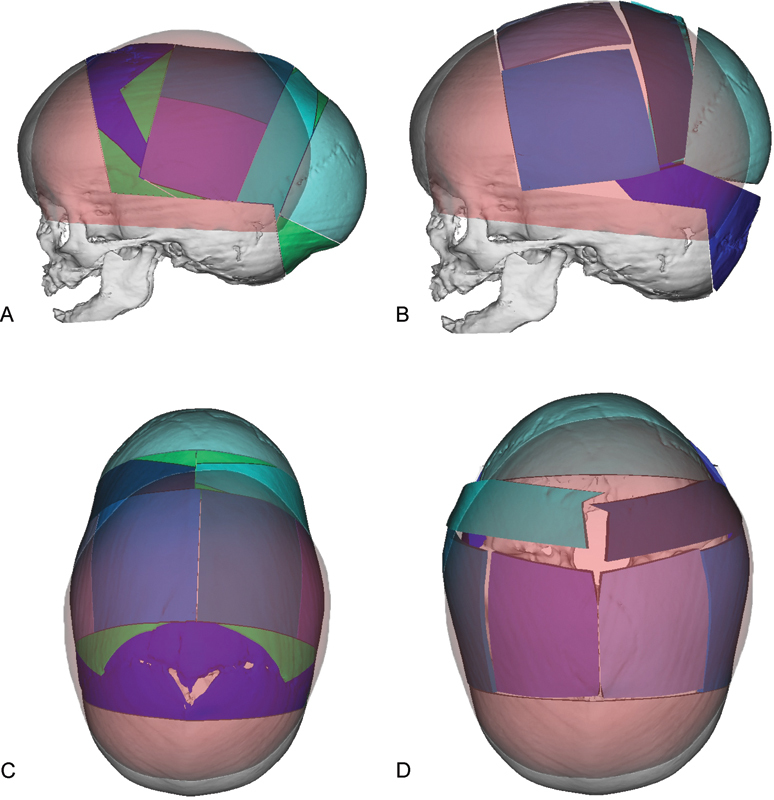
Virtual surgical planning is used to simulate osteotomies and repositioning of bone segments during cranial vault remodeling for correction of sagittal synostosis. “Normal” age matched skull is colored red. Virtual osteotomized segments are shown in blue, green, and purple. (A) Preoperative lateral view showing planned osteotomies based on overlapping a “normal” age matched skull onto the patient's skull. (B) Projected postoperative lateral view following re-shaping of the cranial vault to match the “normal” skull. (C) Preoperative view from the top of the skull showing planned osteotomies. (D) View following re-shaping of the cranial vault to match as age matched “normal”.
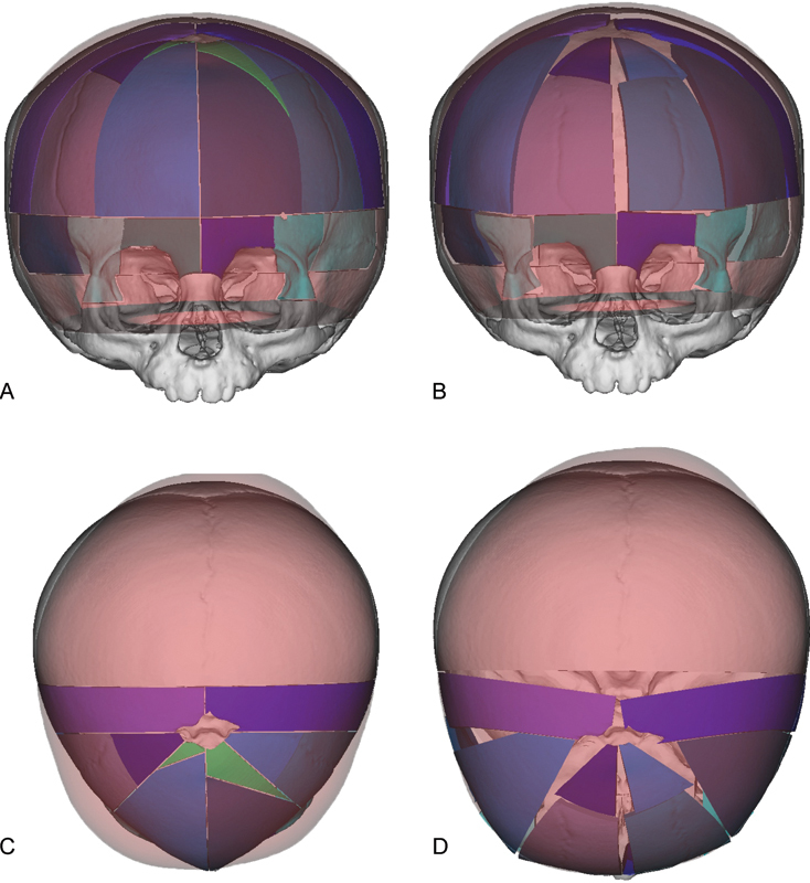
Virtual surgical planning is used to simulate osteotomies and repositioning of bone segments during cranial vault remodeling for correction of metopic synostosis. “Normal” age matched skull is colored red. Virtual osteotomized segments are shown in blue, green, and purple. (A) Preoperative AP view showing planned osteotomies. (B) Projected postoperative AP view following re-shaping of the cranial vault. (C) Preoperative overhead view showing planned osteotomies. (D) Projected postoperative overhead view following re-shaping of the cranial vault shows correction of trigonocephaly.
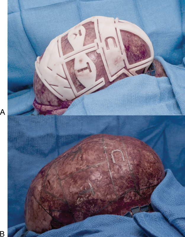
Cutting template allows exact placement of osteotomies and labeling of individual bone segments in a patient with sagittal synostosis. (A) Placement of the template on the calvarium after elevation of the scalp flaps. (B) Marking of planned osteotomies on the calvarium.
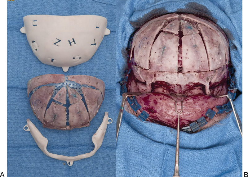
Positioning guides used for placement of individual bone segments to best achieve an age-matched normal calvarial morphology in a patient with metopic synostosis. (A) In this case, bone segments are placed on the internal surface of the template and secured with resorbable plates internally. This can be performed with the bone segments placed on the outside of a positioning guide and plating on the outside. This depends on the preference of the surgeon and the planning of each particular surgery. (B) The reconstructed calvarium is transferred to the patient and further secured with resorbable plates on the external aspect.
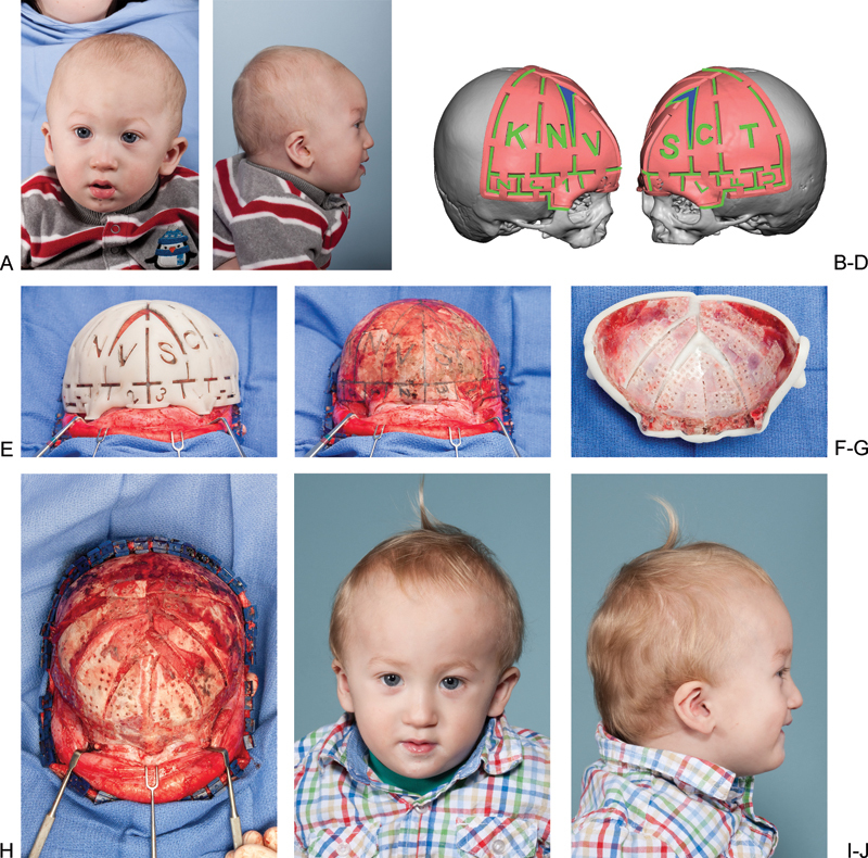
Virtual surgical planning for cranial vault remodeling in a patient with metopic synostosis. (A,B) Preoperative frontal and lateral view of a child with metopic synostosis. (C,D) Oblique views of cutting guides based on VSP of this patients surgery. (E) Cutting guide in place after elevation of the anterior scalp flap. (F) Marking of planned osteotomies on the calvarium. (G) Positioning guide used to reshape bone segments on the back table. (H) Reconstructed anterior cranial vault and supraorbital bar in place. (I,J) Postoperative frontal and lateral view.
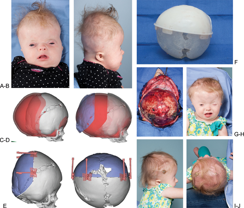
Virtual surgical planning for posterior cranial vault distraction in a syndromic patient with bilateral coronal synostosis. (A,B) Preoperative anteroposterior and lateral view. (C) Overlap of patient's skull with normal age-matched skull (red). (D) Distracted segment (in blue) positioned where it needs to be to achieve normal morphology. (E) Distractors in place in positions that allow for distracting in the planned vector. (F) Cutting guide placed over a three-dimensional model of the patient's abnormal skull. (G) Distractors in placed after osteotomy is performed. (H,I,J) Postoperative views of the patient after 30 mm of distraction performed and prior to removal of distractors.
References
-
- Foley B D, Thayer W P, Honeybrook A, McKenna S, Press S. Mandibular reconstruction using computer-aided design and computer-aided manufacturing: an analysis of surgical results. J Oral Maxillofac Surg. 2013;71(2):e111–e119. - PubMed
-
- Hierl T, Arnold S, Kruber D, Schulze F P, Hümpfner-Hierl H. CAD-CAM-assisted esthetic facial surgery. J Oral Maxillofac Surg. 2013;71(1):e15–e23. - PubMed
-
- Nikkhah D, Ponniah A, Ruff C, Dunaway D. Planning surgical reconstruction in Treacher-Collins syndrome using virtual simulation. Plast Reconstr Surg. 2013;132(5):790e–805e. - PubMed
-
- Tepper O M, Sorice S, Hershman G N, Saadeh P, Levine J P, Hirsch D. Use of virtual 3-dimensional surgery in post-traumatic craniomaxillofacial reconstruction. J Oral Maxillofac Surg. 2011;69(3):733–741. - PubMed
LinkOut - more resources
Full Text Sources
Other Literature Sources
