

Oriented matrix promotes directional tubulogenesis
- PMID: 25219769
- PMCID: PMC4256113
- DOI: 10.1016/j.actbio.2014.08.037
Oriented matrix promotes directional tubulogenesis
Abstract
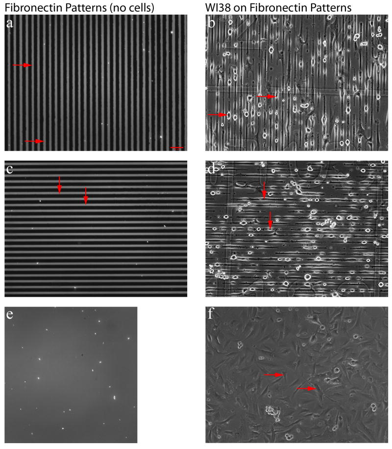
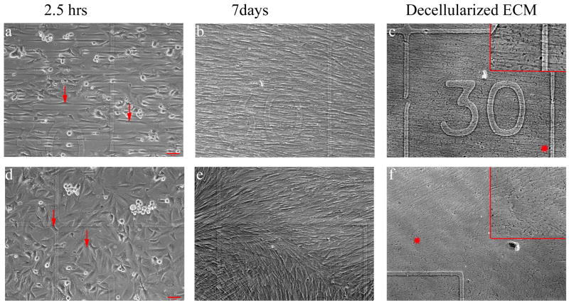
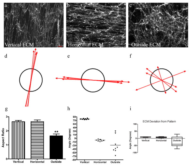
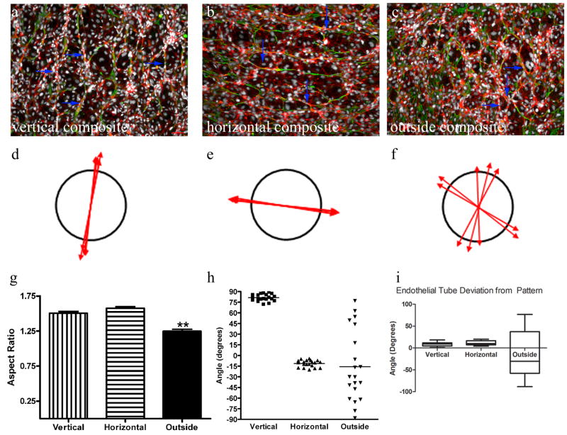
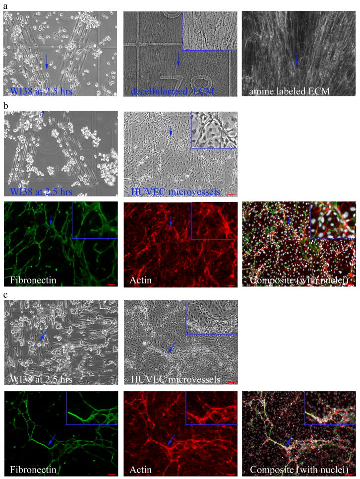
Detailed control over the structural organization of scaffolds and engineered tissue constructs is a critical need in the quest to engineer functional tissues using biomaterials. This work presents a new approach to spatially direct endothelial tubulogenesis. Micropatterned fibronectin substrates were used to control lung fibroblast adhesion and growth and the subsequent deposition of fibroblast-derived matrix during culture. The fibroblast-derived matrix produced on the micropatterned substrates was tightly oriented by these patterns, with an average variation of only 8.5°. Further, regions of this oriented extracellular matrix provided directional control of developing endothelial tubes to within 10° of the original micropatterned substrate design. Endothelial cells seeded directly onto the micropatterned substrate did not form tubes. A metric for matrix anisotropy showed a relationship between the fibroblast-derived matrix and the endothelial tubes that were subsequently developed on the same micropatterns with a resulting aspect ratio over 1.5 for endothelial tubulogenesis. Micropatterns in "L" and "Y" shapes were used to direct endothelial tubes to turn and branch with the same level of precision. These data demonstrate that anisotropic fibroblast-derived matrices instruct the alignment and shape of endothelial tube networks, thereby introducing an approach that could be adapted for future design of microvascular implants featuring organ-specific natural matrix that patterns microvascular growth.
Keywords: Anisotropy; Endothelial morphogenesis; Extracellular matrix; Micropattern substrate.
Copyright © 2014 Acta Materialia Inc. Published by Elsevier Ltd. All rights reserved.
Conflict of interest statement
The products and services described in this article are being developed by Intelligent Substrates. Dr. Hoh and Dr. Heinz are entitled to a share of equity as founders of Intelligent Substrates. Dr. Hoh also served as an advisor to the company, and Dr. Heinz served as the President of the company. Dr. Hoh and Dr. Heinz are also entitled to a share of royalty received by the university on sales of products related to this article. The terms of this arrangement are being managed by the Johns Hopkins University in accordance with its conflict of interest policies.
Figures
Similar articles
-
Endothelial cell adhesion, signaling, and morphogenesis in fibroblast-derived matrix.Matrix Biol. 2009 Jun;28(5):273-83. doi: 10.1016/j.matbio.2009.04.005. Epub 2009 Apr 16. Matrix Biol. 2009. PMID: 19375504
-
Engineered Microvessels for the Study of Human Disease.J Biomech Eng. 2016 Nov 1;138(11):1108011-11080111. doi: 10.1115/1.4034428. J Biomech Eng. 2016. PMID: 27537085 Free PMC article. Review.
-
A self-assembling peptide matrix used to control stiffness and binding site density supports the formation of microvascular networks in three dimensions.Acta Biomater. 2013 Aug;9(8):7651-61. doi: 10.1016/j.actbio.2013.04.002. Epub 2013 Apr 17. Acta Biomater. 2013. PMID: 23603000 Free PMC article.
-
Tuning of cell-biomaterial anchorage for tissue regeneration.Adv Mater. 2013 Aug 7;25(29):4049-57. doi: 10.1002/adma.201301227. Adv Mater. 2013. PMID: 24063035
-
Mechanisms by which acellular biologic scaffolds promote functional skeletal muscle restoration.Biomaterials. 2016 Oct;103:128-136. doi: 10.1016/j.biomaterials.2016.06.047. Epub 2016 Jun 24. Biomaterials. 2016. PMID: 27376561 Review.
Cited by
-
Autophagy Is Polarized toward Cell Front during Migration and Spatially Perturbed by Oncogenic Ras.Cells. 2021 Oct 2;10(10):2637. doi: 10.3390/cells10102637. Cells. 2021. PMID: 34685617 Free PMC article.
-
Patterning of Fibroblast and Matrix Anisotropy within 3D Confinement is Driven by the Cytoskeleton.Adv Healthc Mater. 2016 Jan 7;5(1):146-58. doi: 10.1002/adhm.201500030. Epub 2015 Jun 1. Adv Healthc Mater. 2016. PMID: 26033825 Free PMC article.
-
Fibroblast-Derived Extracellular Matrices: An Alternative Cell Culture System That Increases Metastatic Cellular Properties.PLoS One. 2015 Sep 15;10(9):e0138065. doi: 10.1371/journal.pone.0138065. eCollection 2015. PLoS One. 2015. PMID: 26371754 Free PMC article.
References
-
- Fung Y-C. Biomechanics: mechanical properties of living tissues. New York: Spinger-Verlag; 1993.
-
- Schmedlen RH, Elbjeirami WM, Gobin AS, West JL. Tissue engineered small-diameter vascular grafts. Clin Plast Surg. 2003;30:507–17. - PubMed
-
- Manwaring ME, Walsh JF, Tresco PA. Contact guidance induced organization of extracellular matrix. Biomaterials. 2004;25:3631–8. - PubMed
Publication types
MeSH terms
Grants and funding
LinkOut - more resources
Full Text Sources
Other Literature Sources
