. 2014 Oct;11(5):056023.
doi: 10.1088/1741-2560/11/5/056023. Epub 2014 Sep 22.

Controllable pulse parameter transcranial magnetic stimulator with enhanced circuit topology and pulse shaping

Affiliations

Controllable pulse parameter transcranial magnetic stimulator with enhanced circuit topology and pulse shaping

Angel V Peterchev et al. J Neural Eng. 2014 Oct.

Abstract

Objective: This work aims at flexible and practical pulse parameter control in transcranial magnetic stimulation (TMS), which is currently very limited in commercial devices.

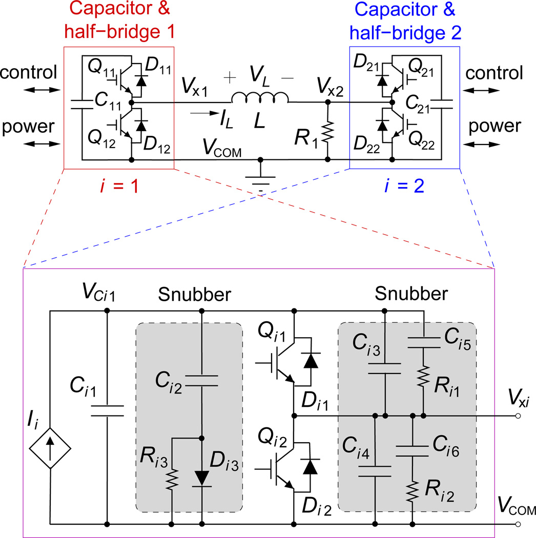
Approach: We present a third generation controllable pulse parameter device (cTMS3) that uses a novel circuit topology with two energy-storage capacitors. It incorporates several implementation and functionality advantages over conventional TMS devices and other devices with advanced pulse shape control. cTMS3 generates lower internal voltage differences and is implemented with transistors with a lower voltage rating than prior cTMS devices.

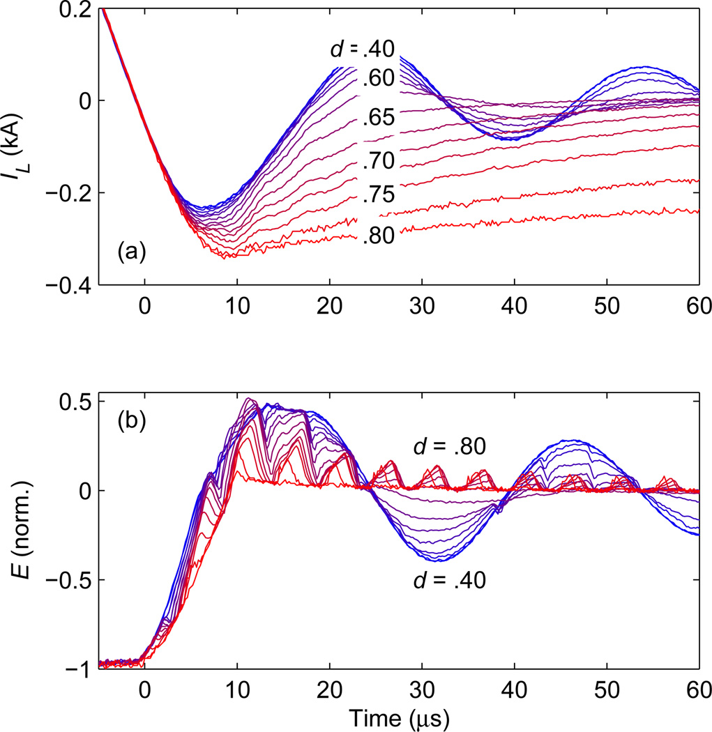
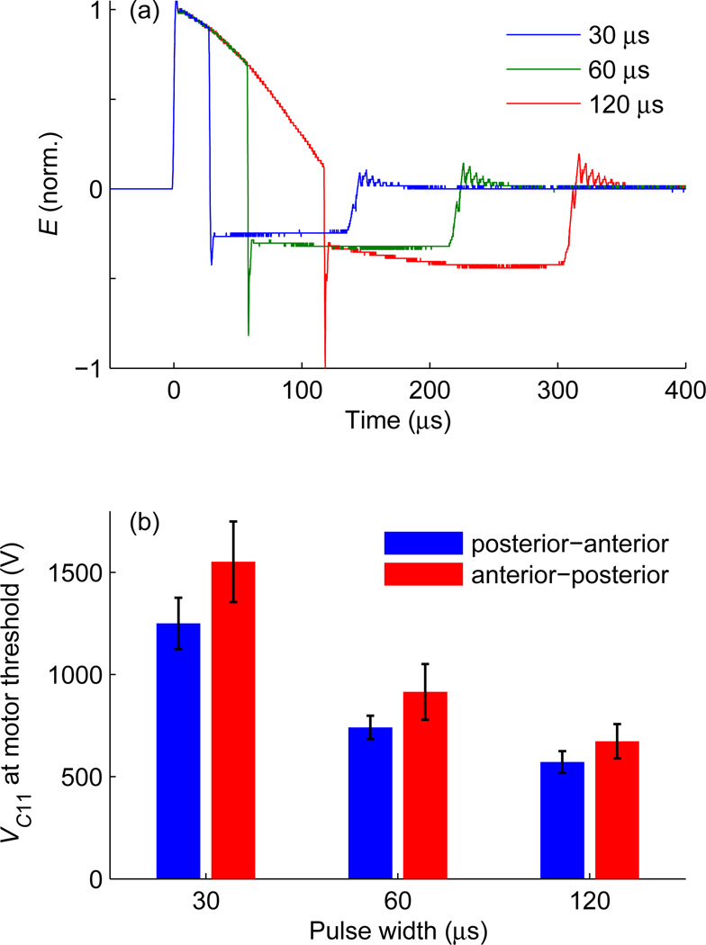
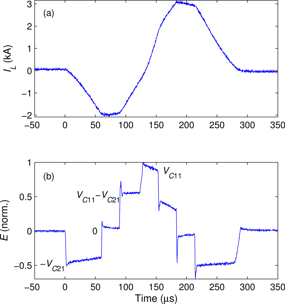
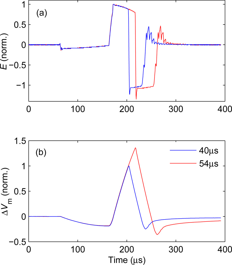
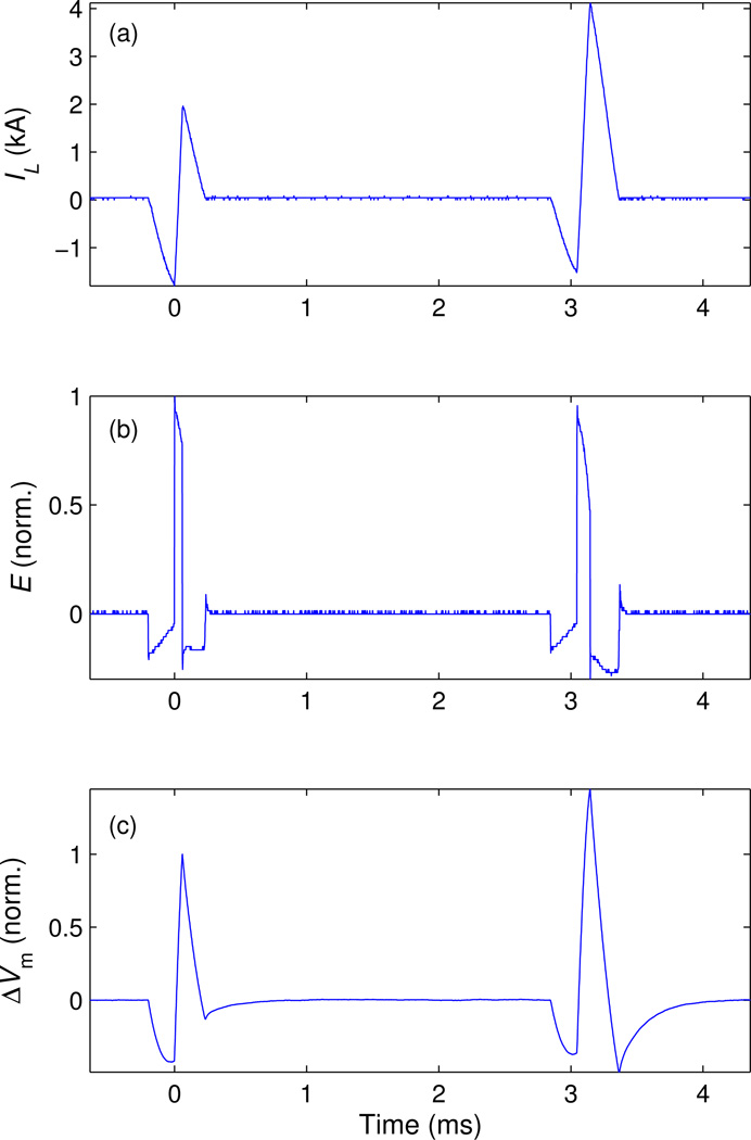
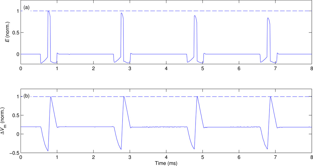
Main results: cTMS3 provides more flexible pulse shaping since the circuit topology allows four coil-voltage levels during a pulse, including approximately zero voltage. The near-zero coil voltage enables snubbing of the ringing at the end of the pulse without the need for a separate active snubber circuit. cTMS3 can generate powerful rapid pulse sequences (< 10 ms inter pulse interval) by increasing the width of each subsequent pulse and utilizing the large capacitor energy storage, allowing the implementation of paradigms such as paired-pulse and quadripulse TMS with a single pulse generation circuit. cTMS3 can also generate theta (50 Hz) burst stimulation with predominantly unidirectional electric field pulses. The cTMS3 device functionality and output strength are illustrated with electrical output measurements as well as a study of the effect of pulse width and polarity on the active motor threshold in ten healthy volunteers.

Significance: The cTMS3 features could extend the utility of TMS as a research, diagnostic, and therapeutic tool.


Figures

Figure 1
Figure 1
Diagram of key elements of the cTMS3 circuit. (top) Two half-bridges connected to energy storage capacitors (i = 1,2) drive differentially the stimulation coil L. (bottom) Each half-bridge, Qi1/Di1Qi2/Di2, is connected to an energy-storage capacitor Ci1 and charge control module Ii. Passive snubber circuits are shown in shaded blocks.
Figure 2
Figure 2
Measured active snubbing at the end of a positive monophasic TMS pulse with peak coil current of IL = 3 kA. Ideally, IL should decay to zero and remain there. However, ringing occurs between the coil and the switch capacitive snubbers. To dampen these oscillations, transistor Q12 is switched with a period of 5 µs and various duty ratios d. (a) Coil current IL and (b) corresponding induced electric field strength E are shown for a d range of 0.4–0.8 [d values printed over the traces in (a)]. For d > 0.625, the response transitions from underdamped to overdamped.
Figure 3
Figure 3
Motor threshold measurement in 10 human subjects as a function of pulse width and current direction. (a) Measured electric field waveform E of monophasic magnetic pulses with VC21 = 0.2VC11 and positive phase widths of 30, 60, and 120 µs. (b) Active motor thresholds for the three pulse widths with posterior–anterior and anterior–posterior direction of the initial phase of the induced current. Bars give mean values and whiskers give standard deviation. For comparison, the active motor threshold with a conventional monophasic TMS device (Magstim 200) is 1044±252 V [32].
Figure 4
Figure 4
Measured waveforms of (a) coil current IL and (b) electric field E for a synthesized staircase pulse illustrating the four E levels that can be achieved within each pulse. Coil voltages corresponding to each E level are indicated in (b). Initial energy-storage capacitor voltages are VC11 = 1430 V and VC21 = 0.5VC11.
Figure 5
Figure 5
(a) Measured electric field waveform E and (b) estimated neural membrane depolarization ΔVm for a pulse approximating minimum energy pulses [34]. The initial capacitor voltages are VC11 = 816 V and VC21 = 1.1VC11. The duration of the initial negative E phase is 100 µs and the width of the second, positive phase is either 40 µs (blue curves) or 54 µs (red curves).
Figure 6
Figure 6
Pair of biphasic pulses delivered with short interstimulus interval (3 ms). The plots show measurements of (a) coil current IL and (b) electric field E, as well as (c) modeled neural membrane depolarization ΔVm. The parameters of the first pulse are VC11 = 1196 V, VC21 = 0.22VC11, and positive E phase width of 60 µs. In the second pulse, the positive E phase width is increased to 100 µs, resulting in larger membrane depolarization despite the reduced E amplitude.
Figure 7
Figure 7
Four pulses separated by inter stimulus interval of 2 ms forming a quadripulse burst [36]. The plots show (a) measured electric field waveform E (filtered with 3-point median filter to illustrate clearly pulse amplitude by removing switching spikes) and (b) estimated neural membrane depolarization ΔVm. The initial capacitor voltages are VC11 = 1230 V and VC21 =0.22VC11, and the duration of the first, negative phase of the electric field pulses is fixed at 200 µs. In order to compensate for the reduction of charge on the capacitors due to energy loss and the consequent reduction of pulse amplitude, the duration of the second, positive electric field phase is increased for each subsequent pulse, having values of 67, 69, 73, and 78 µs, respectively.

References

    1. Peterchev AV, Wagner TA, Miranda PC, Nitsche MA, Paulus W, Lisanby SH, Pascual-Leone A, Bikson M. Fundamentals of transcranial electric and magnetic stimulation dose: Definition, selection, and reporting practices. Brain Stimul. 2012;5:435–453. - PMC - PubMed
    1. Heise K-F, Zimerman M, Hoppe J, Gerloff C, Wegscheider K, Hummel FC. The aging motor system as a model for plastic changes of GABA-mediated intracortical inhibition and their behavioral relevance. J Neurosci. 2013;33:9039–9049. - PMC - PubMed
    1. Quartarone A, Bagnato S, Rizzo V, Siebner HR, Dattola V, Scalfari A, Morgante F, Battaglia F, Romano M, Girlanda P. Abnormal associative plasticity of the human motor cortex in writer’s cramp. Brain. 2003;126:2586–2596. - PubMed
    1. Sailer A, Molnar GF, Paradiso G, Gunraj CA, Lang AE, Chen R. Short and long latency afferent inhibition in Parkinson’s disease. Brain. 2003;126:1883–1894. - PubMed
    1. O’Reardon JP, Solvason HB, Janicak PG, Sampson S, Isenberg KE, Nahas Z, McDonald WM, Avery D, Fitzgerald PB, Loo C, Demitrack MA, George MS, Sackeim HA. Efficacy and safety of transcranial magnetic stimulation in the acute treatment of major depression: a multisite randomized controlled trial. Biol Psych. 2007;62(11):1208–1216. - PubMed

Publication types

MeSH terms