. 2014 Nov 10;15(11):3891-900.
doi: 10.1021/bm500874t. Epub 2014 Oct 17.

Engineering complementary hydrophobic interactions to control β-hairpin peptide self-assembly, network branching, and hydrogel properties

Affiliations

Engineering complementary hydrophobic interactions to control β-hairpin peptide self-assembly, network branching, and hydrogel properties

Sameer Sathaye et al. Biomacromolecules. .

Abstract

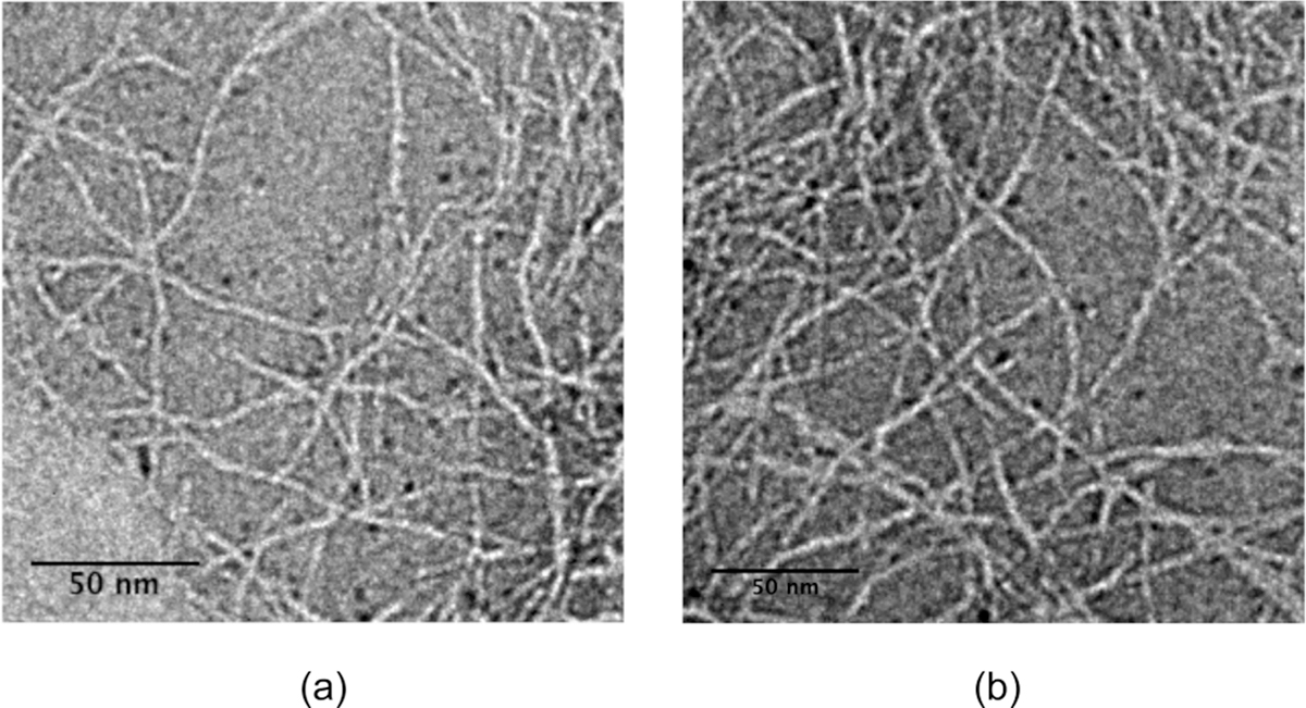
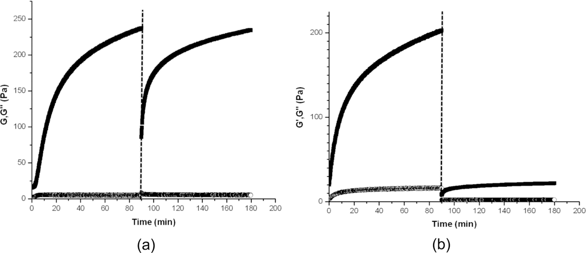
The MAX1 β-hairpin peptide (VKVKVKVK-V(D)PPT-KVKVKVKV-NH2) has been shown to form nanofibrils having a cross-section of two folded peptides forming a hydrophobic, valine-rich core, and the polymerized fibril exhibits primarily β-sheet hydrogen bonding.1-7 These nanofibrils form hydrogel networks through fibril entanglements as well as fibril branching.8 Fibrillar branching in MAX1 hydrogel networks provide the ability to flow under applied shear stress and immediately reform a hydrogel solid on cessation of shear. New β-hairpins were designed to limit branching during nanofibril growth because of steric specificity in the assembled fibril hydrophobic core. The nonturn valines of MAX1 were substituted by 2-naphthylalanine (Nal) and alanine (A) residues, with much larger and smaller side chain volumes, respectively, to obtain LNK1 (Nal)K(Nal)KAKAK-V(D)PPT-KAKAK(Nal)K(Nal)-NH2. LNK1 was targeted to self-associate with a specific "lock and key" complementary packing in the hydrophobic core in order to accommodate the Nal and Ala residue side chains. The experimentally observable manifestation of reduced fibrillar branching in the LNK1 peptide is the lack of solid hydrogel formation after shear in stark contrast to the MAX1 branched fibril system. Molecular dynamics simulations provide a molecular picture of interpeptide interactions within the assembly that is consistent with the branching propensity of MAX1 vs LNK1 and in agreement with experimental observations.


Conflict of interest statement

The authors declare no competing financial interest.

Figures

Figure 1.
Figure 1.
Ribbon representations of MAX1 and LNK1. MAX1 can form branched nanofibrils. LNK1 is restrained to form only linear fibrils. The inserts are views of fibrillar cross sections. In MAX1, valine residues form a nonspecific, “flat” hydrophobic interface. In LNK1, specific hydrophobic steric interactions appear as wel as the interior hydrophobic interface between complementary naphthylalanine and alanine side chains.
Figure 2.
Figure 2.
Circular dichroism data (mean residue ellipticity in deg·cm/decimole at 218 nm v/s temperature °C) showing approximately the same folding transition temperature (∼30 °C) from random coil to β-sheet secondary conformation for both MAX1 and LNK1.
Figure 3.
Figure 3.
Transmission electron micrographs of (a) MAX1 and (b) LNK1. Samples were prepared at pH 7, 50 mM Bis-tris propane, 150 mM NaCl buffer, and stained with 1% (w/v) uranyl acetate in deionized water.
Figure 4.
Figure 4.
Oscillatory time sweep measurements before and after application of steady-state shear (1000/s for 120 s, indicated by dotted line) on 0.5% (w/v) (a) MAX1 and (b) LNK1 networks under the same solution conditions (pH 9 125 mM Boric Acid 10 mM NaCl). Solid squares indicate G′ (Pa) and open circles G″ (Pa).
Figure 5.
Figure 5.
Oscillatory frequency sweep (a) MAX1 and (b) LNK1 measurements after application of injection shear treatment to both networks formed under the same solution conditions (pH 9 125 mM boric acid, 10 mM NaCl). Solid squares indicate G′ (Pa) and open circles G″ (Pa). Transmission electron micrographs of (c) MAX1 and (d) LNK1 post injection shear treatment.
Figure 6.
Figure 6.
Renderings of representative equilibrium structures of (a) MAX1 octamer after 70 ns and (b) LNK1 octamer after 70 ns. Orthogonal views are shown for each. Coloring is used to distinguish layers in bilayer structure of each fibrillar assembly. The molecular structure of LNK1 presents a specific “lock and key” packing style between size-complementary Nal and Ala residues. “Aromatic ladder” of Nal residues is shown in the panel on the right in Figure 4b (Thr and Val residues are omitted from this figure for clarity).
Figure 7.
Figure 7.
(a) Representative conformations of the MAX1 model at different crossing angles. The top series of structures show the extent of the crossing angle θ. The bottom series presents qualitative visualization of the twist and gradual exposure of hydrophobic surface as the crossing angle decreases. (b) Modeled MAX1 branch point from two perspectives. Transparent regions (not sampled from the simulation) are modeled based upon the MAX1 configuration at θ =160° and positioned along the fibril growth direction. (c) Distributions of crossing angle θ for MAX1 (blue) and LNK1 (red). Sampled configurations are obtained from five simulations of MAX1 and six simulations of LNK1. Representative structures of MAX1 (θ =167°) and LNK1 (θ =175°) from the simulations are rendered. Sampled configurations are collected every 10 ps after the first 20 ns for each MAX1 simulation and after the first 15 ns for the LNK1 simulations.

References

    1. Schneider JP; Pochan DJ; Ozbas B; Rajagopal K; Pakstis L; Kretsinger J J. Am. Chem. Soc 2002, 124, 15030. - PubMed
    1. Pochan D; Schneider J Biopolymers 2003, 71, 317.
    1. Pochan DJ; Schneider JP; Kretsinger J; Ozbas B; Rajagopal K; Haines L J. Am. Chem. Soc 2003, 125, 11802. - PubMed
    1. Ozbas B; Kretsinger J; Rajagopal K; Schneider JP; Pochan DJ Macromolecules 2004, 37, 7331.
    1. Ozbas B; Rajagopal K; Schneider JP; Pochan DJ Phys. Rev. Lett 2004, 93. - PubMed

Publication types

MeSH terms