

Liquid crystal-enabled electro-osmosis through spatial charge separation in distorted regions as a novel mechanism of electrokinetics
- PMID: 25255307
- PMCID: PMC4200513
- DOI: 10.1038/ncomms6033
Liquid crystal-enabled electro-osmosis through spatial charge separation in distorted regions as a novel mechanism of electrokinetics
Abstract
Electrically controlled dynamics of fluids and particles at microscales is a fascinating area of research with applications ranging from microfluidics and sensing to sorting of biomolecules. The driving mechanisms are electric forces acting on spatially separated charges in an isotropic medium such as water. Here, we demonstrate that anisotropic conductivity of liquid crystals enables new mechanism of highly efficient electro-osmosis rooted in space charging of regions with distorted orientation. The electric field acts on these distortion-separated charges to induce liquid crystal-enabled electro-osmosis. Their velocities grow with the square of the field, which allows one to use an alternating current field to drive steady flows and to avoid electrode damage. Ionic currents in liquid crystals that have been traditionally considered as an undesirable feature in displays, offer a broad platform for versatile applications such as liquid crystal-enabled electrokinetics, micropumping and mixing.
Figures

 and (b) azimuthal
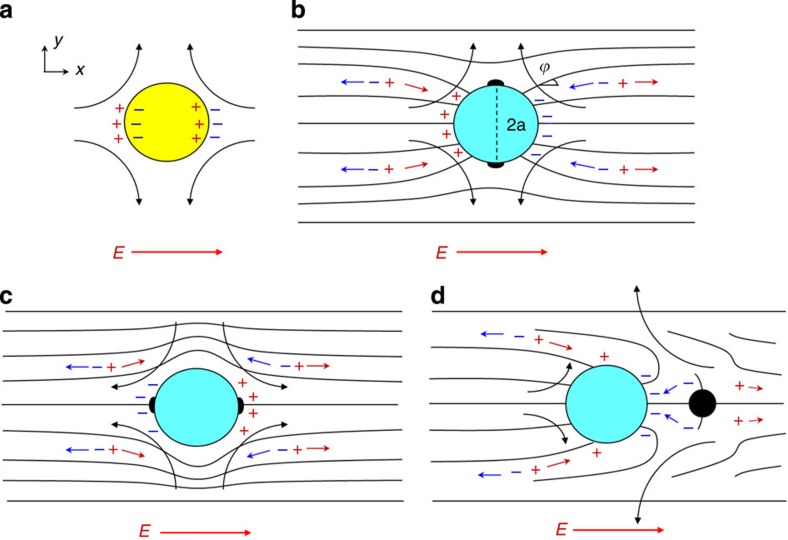
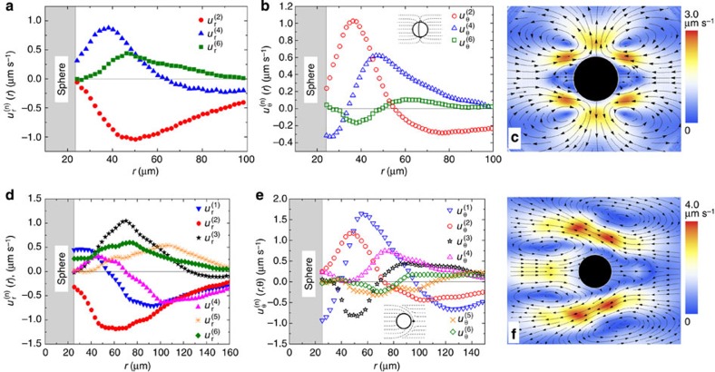
  coefficients for LCEO flows triggered by a quadrupolar director pattern, Fig. 2b; (c) velocity field reconstructed with the three harmonics that show a close similarity to the experimental data in Fig. 2b; (d–f), the same, but for a sphere with a dipolar director and LCEO pumping, compare with Fig. 2f. Particle diameter 2a=50 μm.
References
-
- Ramos A. inElectrokinetics and Electrohydrodynamics in Microsystems ed Ramos A. Springer (2011).
-
- Morgan H. & Green N. G. AC Electrokinetics: Colloids and Nanoparticles Research Studies Press Ltd (2003).
-
- Squires T. M. & Bazant M. Z. Induced-charge electro-osmosis. J. Fluid. Mech. 509, 217–252 (2004).
-
- Squires T. M. & Bazant M. Z. Breaking symmetries in induced-charge electro-osmosis and electrophoresis. J. Fluid. Mech. 560, 65–102 (2006).
-
- Bazant M. Z. & Squires T. M. Induced-charge electrokinetic phenomena. Curr. Opin. Colloid Interface Sci. 15, 203–213 (2010).
Publication types
LinkOut - more resources
Full Text Sources
Other Literature Sources
