Review
. 2014 Oct 1;2014(10):pdb.top071795.
doi: 10.1101/pdb.top071795.

Fluorescence microscopy

Affiliations
Review

Fluorescence microscopy

Michael J Sanderson et al. Cold Spring Harb Protoc. .

Abstract

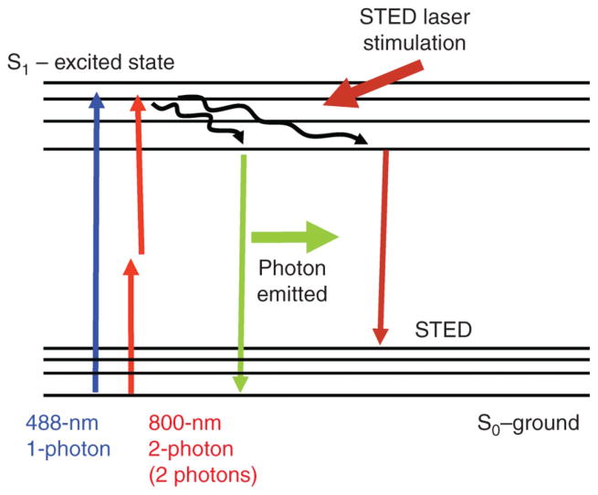
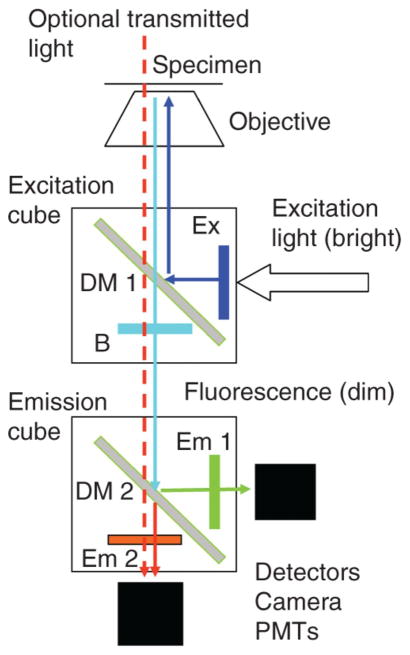
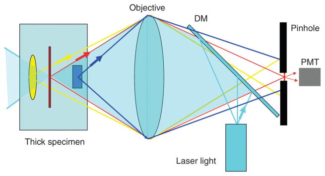
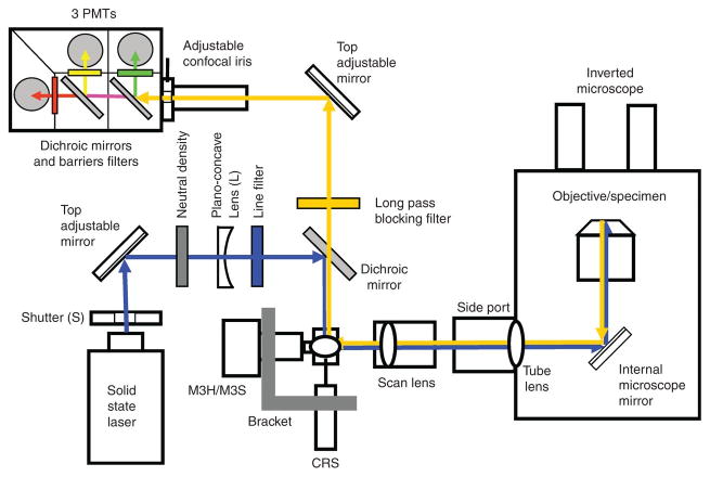
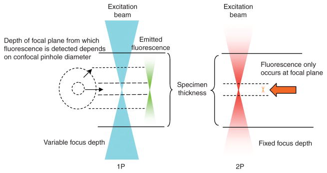
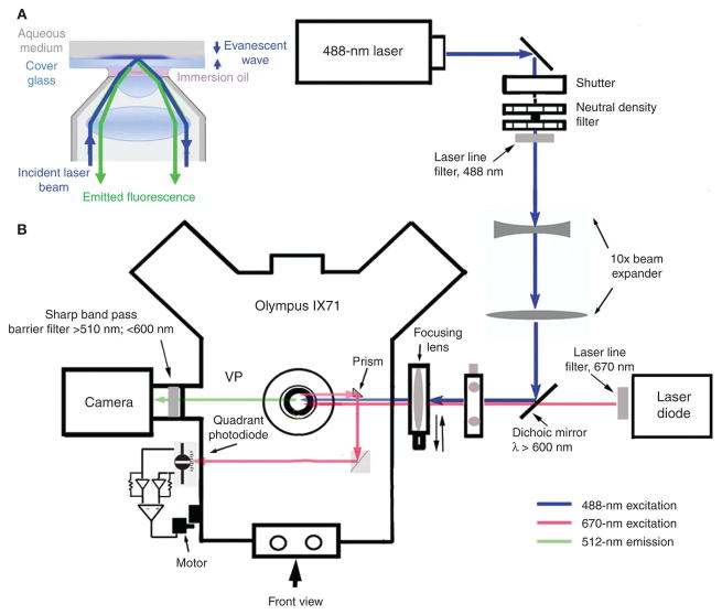
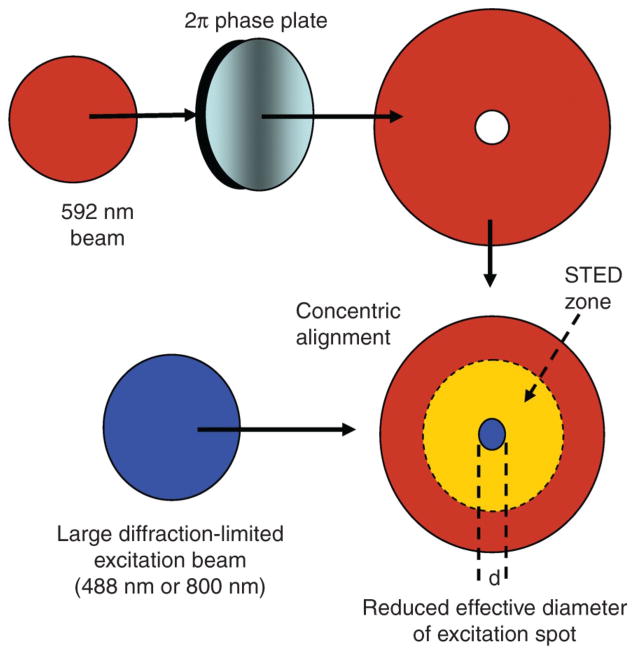
Fluorescence microscopy is a major tool with which to monitor cell physiology. Although the concepts of fluorescence and its optical separation using filters remain similar, microscope design varies with the aim of increasing image contrast and spatial resolution. The basics of wide-field microscopy are outlined to emphasize the selection, advantages, and correct use of laser scanning confocal microscopy, two-photon microscopy, scanning disk confocal microscopy, total internal reflection, and super-resolution microscopy. In addition, the principles of how these microscopes form images are reviewed to appreciate their capabilities, limitations, and constraints for operation.


Figures

Figure 1
Figure 1
Changes in electron state of fluorescent indicators during photon excitation and emission (Jablonski profiles). Excitation (from S0 to S1) induced by 488 nm laser light (blue) requires one photon or by two-photon 800 nm light (red) requires two photons. After relaxation to the lowest energy levels, the reverse transition (from S1 to S0) releases a photon of longer wavelength (green). The incidence of photons at 592 nm (STED wavelength) induces the transition from S1 to high levels of S0 and suppression of fluorescence.
Figure 2
Figure 2
The basic light paths of a fluorescence microscope. An excitation filter cube containing a dichroic mirror (DM 1) directs excitation light (from a bulb or laser; filtered with an excitation filter) to the specimen and passes emitted fluorescence to the emission cube for further separation (multiple indicators). The barrier filter B prevents excitation light from reaching the detectors. Emitted fluorescence is separated by DM 2 into two beams. The emission filters (Em 1 and Em 2) block unwanted light. Fluorescence is detected by cameras (wide-field) or PMTs (laser-scanning). For transmitted illumination of a bright-field image, long wavelength light is selected.
Figure 3
Figure 3
Principle of operation of a laser scanning confocal microscope. Laser light is focused on the thick specimen by reflection from the dichroic mirror (DM) and the objective lens. The laser excites fluorescence throughout the specimen that passes through the DM and is focused onto the image plane. A pinhole only allows light from the confocal plane of the specimen to reach the photomultiplier tube (PMT).
Figure 4
Figure 4
Basic elements of a laser scanning confocal microscope. Laser light is directed to the scan mirrors via a dichroic mirror. The laser is scanned across the specimen by the scan mirrors and the returning emitted fluorescence is descanned by the same mirrors and transmitted by the dichroic mirror. The fluorescence passes through the barrier filter and is focused on to the pinhole (adjustable iris) before reaching the PMTs. Additional dichroic mirrors can be used to separate fluorescence wavelengths.
Figure 5
Figure 5
Determination of depth-of-field and bleaching in one- or two-photon microscopy. In one-photon microscopy (1P, blue), a cone of excitation light on either side of the focal point illuminates and excites the fluorescence indicator throughout the specimen. The size of the pinhole determines the depth of fluorescence detection. In two-photon microscopy (2P, red), the photon density is only sufficiently high at the focal plane to induce indicator fluorescence. This beam has a fixed depth of excitation.
Figure 6
Figure 6
Images collected with a resonant scanner. Left image shows distortion resulting from the slowing of the scan toward the image edges. Right image shows the same image after correction that linearizes the scan rate to remove edge distortion.
Figure 7
Figure 7
Basic elements of a two-photon microscope. PMTs detectors do not require pinholes or focused images and are located immediately below the objective. The design is for the most part similar to that of the one-photon laser scanning confocal microscope; see Figure 4.
Figure 8
Figure 8
Concept of trans-illumination: for fluorescence, second-harmonic, and conventional light imaging. Two-photon (red) excitation illuminates the specimen. Second harmonic (blue) or fluorescence (green) light are transmitted and collected by PMTs after separation by a dichroic mirror (DM). Two-photon light is transmitted by the DM to produce a transmitted light image. Reflected fluorescence is detected after DM (bottom right image). Top image is the combined transmitted and reflected fluorescence image with increased signal-to-noise ratio.
Figure 9
Figure 9
Through-the-objective TIRF microscopy: (A) schematic illustrating the formation of an evanescent wave by a laser beam directed through a high-NA objective to undergo total internal reflection at the interface between a glass coverslip and aqueous medium. Fluorescence emitted by a fluorophore excited by the evanescent wave is collected back through the same objective. (B) Layout of a TIRF imaging system based on an inverted microscope. Translation of the focusing lens is used to control the position of the excitation laser spot at the objective back aperture and thereby alter the angle of incidence at the interface between the coverslip and aqueous medium. The system includes a separate deep-red laser for feedback control of microscope focus.
Figure 10
Figure 10
Creation of reduced excitation spot for STED microscopy. The STED (592-nm) laser beam (red) is shaped by a 2π phase plate into a doughnut and concentrically overlaid with the 488-nm excitation laser (blue). The process of STED occurs in the yellow zone to reduce the zone of fluorescence. Increased STED laser power decreases the diameter, d, of the excitation spot.

References

    1. Abbe E. Contributions to the theory of the microscope and of microscopic resolution. Arch f Mikr Anat. 1873:413–420.
    1. Ambrose EJ. A surface contact microscope for the study of cell movements. Nature. 1956;178:1194. - PubMed
    1. Axelrod D. Total internal reflection fluorescence microscopy in cell biology. Methods Enzymol. 2003;361:1–33. - PubMed
    1. Bai Y, Edelmann M, Sanderson MJ. The contribution of inositol 1,4,5-trisphosphate and ryanodine receptors to agonist-induced Ca2+ signaling of airway smooth muscle cells. Am J Physiol Lung Cell Mol Physiol. 2009;297:L347–L361. - PMC - PubMed
    1. Betzig E, Patterson GH, Sougrat R, Lindwasser OW, Olenych S, Bonifacino JS, Davidson MW, Lippincott-Schwartz J, Hess HF. Imaging intracellular fluorescent proteins at nanometer resolution. Science. 2006;313:1642–1645. - PubMed

Publication types