. 2014 Oct 9:5:5093.
doi: 10.1038/ncomms6093.

Magneto-fluorescent core-shell supernanoparticles

Affiliations

Magneto-fluorescent core-shell supernanoparticles

Ou Chen et al. Nat Commun. .

Abstract

Magneto-fluorescent particles have been recognized as an emerging class of materials that exhibit great potential in advanced applications. However, synthesizing such magneto-fluorescent nanomaterials that simultaneously exhibit uniform and tunable sizes, high magnetic content loading, maximized fluorophore coverage at the surface and a versatile surface functionality has proven challenging. Here we report a simple approach for co-assembling magnetic nanoparticles with fluorescent quantum dots to form colloidal magneto-fluorescent supernanoparticles. Importantly, these supernanoparticles exhibit a superstructure consisting of a close-packed magnetic nanoparticle 'core', which is fully surrounded by a 'shell' of fluorescent quantum dots. A thin layer of silica coating provides high colloidal stability and biocompatibility, and a versatile surface functionality. We demonstrate that after surface pegylation, these silica-coated magneto-fluorescent supernanoparticles can be magnetically manipulated inside living cells while being optically tracked. Moreover, our silica-coated magneto-fluorescent supernanoparticles can also serve as an in vivo multi-photon and magnetic resonance dual-modal imaging probe.


Conflict of interest statement

Competing financial interests

The authors declare no competing financial interests.

Figures
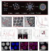
Figure 1
Figure 1. Synthesis and characterizations of core-shell structured SPs
a, Schematic of the formation of the core-shell supernanoparticles (CS-SPs). b–d, A set of TEM images of CS-SPs at different magnifications. Scale bars in b–d are 500 nm, 100 nm and 10 nm, respectively. e, Absorption spectra of CS-SPs (blue), MNPs (green), QDs (purple) and photoluminescence spectrum of CS-SPs (red). f, Wide-angle X-ray scattering pattern of CS-SPs. The stick patterns show the standard peak positions of bulk Fe3O4 (magnetite, bottom blue sticks) and wurtzite CdS (top green sticks). g, Photographs demonstrating the magnetic attraction of CS-SPs in the presence of a magnet under both room and UV light. h, Energy-dispersive X-ray spectrum (EDS) of CS-SPs shown in b–d. i, Images of dark-field scanning TEM and EDS elemental mapping from CS-SPs. Scale bars are 80 nm. j, EDS elemental line scan result. Scale bar is 60 nm.
Figure 2
Figure 2. Supercrystalline CS-SPs and their size-controlled syntheses
TEM images of super-crystalline CS-SPs viewed along different zone axes a, [001], b, [110] and c, [11̄2̄]. d, TEM image of a CS-SP with a stacking fault marked with a yellow arrow. Scale bars in a–d are 50 nm. e, The integrated data from the small-angle X-ray scattering (SAXS) pattern (inset) of CS-SPs show a position ratio series of q/q0=1/4/3/8/3/11/3/4/19/3/8/9/12, (q0 is the position of the (111) peak, q =4πsinθ/λ), indicating a face-centered-cubic (fcc) close-packing of the MNPs. Large area TEM images (f–i) and higher magnification TEM images (j–m) of CS-SPs with an average diameter of 80 ± 9 nm (f, j), 120 ± 13 nm (g, k), 235 ± 30 nm (h, l) and 360 ± 60 nm (i, m). The insets in panel l and m are zoomed-in images of the blue squares. Scale bars in f–i are 500 nm. Scale bars in j–m are 30 nm, 50 nm, 70 nm and 100 nm, respectively. Scale bars in the insets of l and m are 15 nm. Red and yellow circles indicate the positons of QDs and MNPs, respectively.
Figure 3
Figure 3. Silica-coated CS-SPs
a, A representative TEM image of silica-coated CS-SPs (silica-CS-SPs) with a thin layer thickness of ~ 10.6 ± 0.7 nm. Scale bar is 200 nm. Insets show the histogram of the particle diameter distribution of silica-CS-SPs with an average diameter of 100 ± 12 nm (top right) and a zoomed-in TEM image of one silica-CS-SP (bottom right). Scale bar in the inset is 50 nm. b, An image of dark-field scanning TEM (STEM) and elemental line scan from a silica-CS-SP show that, while maintaining the core-shell superstructure, a thin layer of silica shell is uniformly deposited onto the CS-SP’s surface. Scale bar is 50 nm. c, HD diameter and relative photoluminescence (relat. PL) intensity of silica-CS-SPs as a function of storage time. d, Magnetic characterization (magnetization versus magnetic field at 300K) shows the superparamagnetism of silica-CS-SPs. e, Left, epi fluorescence image of silica-CS-SPs on a glass substrate. Right, a representative photoluminescence time trace of a single silica-CS-SP.
Figure 4
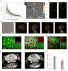
Figure 4. Silica-CS-SPs in biological applications
a, Force applied to individual silica-CS-SPs as a function of the distance from the magnetic tip (Supplementary Movie 6). A power law (red curve) fits the data. b, Tracking of individual silica-CS-SPs during their manipulation inside a Cos7 cell (Supplementary Movie 4). Positions along each trajectory are color-coded according to the time. Scale bar is 15 μm. c, Left: Fluorescence imaging of individual silica-CS-SPs (yellow) in the dashed line region of panel b and before the manipulation. The barycenter of the individual localizations is shown as a yellow cross. Right: superposition of the silica-CS-SPs fluorescence after 2 minutes (red), the barycenter of the individual localizations is shown as a red cross. d, Left: Transmission picture of a Hela cell in which silica-CS-SPs have been microinjected. By bringing the magnetic tip in and out (blue bars), a reversible accumulation of silica-CS-SPs (yellow region) can be created at the cell periphery (indicated by red dashed line), in the direction of the magnetic tip (Supplementary Movie 5). Scale bar is 15 μm. Methoxy-polyethylene-glycol silane (mPEG-silane, MW5000) functionalized silica-CS-SPs (200μL, 2mg/mL) were intravenously injected into C3H mice bearing brain metastasis of a murine mammary carcinoma (MCaIV) with a cranial window model. Intravital multiphoton microscopy through the cranial window was carried out at different time point: pre-injection (e), 4-hour post-injection (f), and 24-hour post-injection (g). Scale bar is 150 μm. Images from red and green channels are shown in small panels (top: red channel, bottom: green channel). Green emission signals are generated from a blood vessel tracer (Fluorescein isothiocyanate–dextran, FITC-Dextran) and red emission signals are generated by mPEG functionalized silica-CS-SPs. In vivo T2-weighted magnetic resonance images of pre- (h) and 24-hour post- (i) injection of mPEG-silane functionalized silica-CS-SPs. 24-hour post-injection image show clear tumor visualization (denoted by the red-dash line). Scale bar is 3 mm. j, The corresponding T2 relaxation (relax.) time fitting results for the tumor region at time points of pre-injection (Pre., blue bar) and 24-hour post-injection (Post., red bar). n = 5 mice, *** P < 0.001 (Student’s t test).

References

    1. Gibson RF. A review of recent research on mechanics of multifunctional composite materials and structures. Compos Struct. 2010;92:2793–2810.
    1. Suh WH, Suh YH, Stucky GD. Multifunctional nanosystems at the interface of physical and life sciences. Nano Today. 2009;4:27–36.
    1. Bigall NC, Parak WJ, Dorfs D. Fluorescent, magnetic and plasmonic-Hybrid multifunctional colloidal nano objects. Nano Today. 2012;7:282–296.
    1. Lee JE, Lee N, Kim T, Kim J, Hyeon T. Multifunctional mesoporous silica nanocomposite nanoparticles for theranostic applications. Accounts Chem Res. 2011;44:893–902. - PubMed
    1. Macfarlane RJ, et al. Nanoparticle superlattice engineering with DNA. Science. 2011;334:204–208. - PubMed

Publication types

MeSH terms