Review
. 2014 Sep;17(5):401-19.
doi: 10.4103/0972-0707.139820.

The self-adjusting file (SAF) system: An evidence-based update

Affiliations
Review

The self-adjusting file (SAF) system: An evidence-based update

Zvi Metzger. J Conserv Dent. 2014 Sep.

Abstract

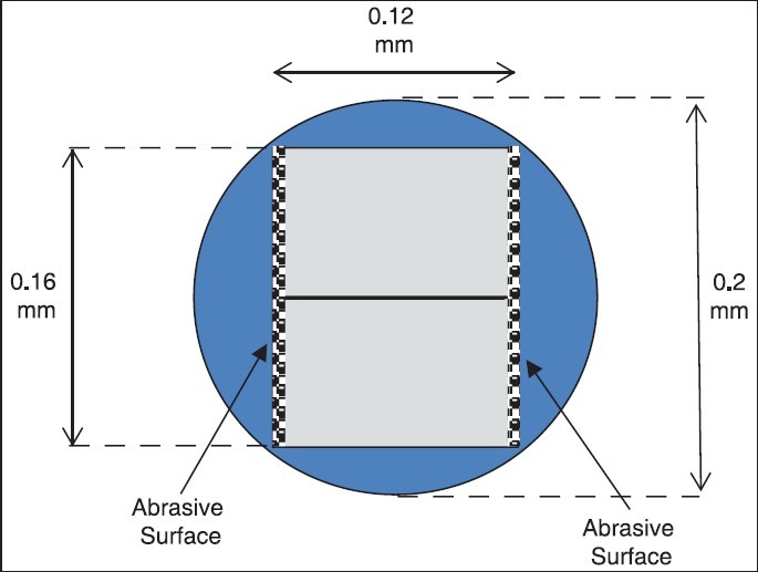
Current rotary file systems are effective tools. Nevertheless, they have two main shortcomings: They are unable to effectively clean and shape oval canals and depend too much on the irrigant to do the cleaning, which is an unrealistic illusionThey may jeopardize the long-term survival of the tooth via unnecessary, excessive removal of sound dentin and creation of micro-cracks in the remaining root dentin. The new Self-adjusting File (SAF) technology uses a hollow, compressible NiTi file, with no central metal core, through which a continuous flow of irrigant is provided throughout the procedure. The SAF technology allows for effective cleaning of all root canals including oval canals, thus allowing for the effective disinfection and obturation of all canal morphologies. This technology uses a new concept of cleaning and shaping in which a uniform layer of dentin is removed from around the entire perimeter of the root canal, thus avoiding unnecessary excessive removal of sound dentin. Furthermore, the mode of action used by this file system does not apply the machining of all root canals to a circular bore, as do all other rotary file systems, and does not cause micro-cracks in the remaining root dentin. The new SAF technology allows for a new concept in cleaning and shaping root canals: Minimally Invasive 3D Endodontics.

Keywords: Cleaning and shaping; NiTi files; SAF; instrumentation; irrigation; minimally invasive; obturation; root filling; rotary files; self-adjusting file.


Conflict of interest statement

Conflict of Interest: Dr. Metzger serves as a Scientific Advisor to ReDent-Nova, manufacturer of the SAF System.

Figures

Figure 1
Figure 1
The Self-adjusting File. (a) The file. (b) Magnification of the lattice structure. Note the two longitudinal beams connected to each other by specially designed arches. The arches are connected to each other with thin struts to prevent them from being pulled out of the tube-like structure
Figure 2
Figure 2
The Self-adjusting File. (a) The rough surface of the file. All components of the file have this rough surface. (b) The asymmetrical tip of the file. (c) Flexibility of the file. As this file is used as the final file, its flexibility should be compared to that of the last, largest file of any rotary file system
Figure 3
Figure 3
Compressibility of the SAF. Left: The file in its relaxed form. (a) The SAF inserted into a canal prepared by a #20 K file. (b) The #20 K file with which the canal was prepared
Figure 4
Figure 4
Adaptation of the SAF to an oval cross-section. The SAF inserted into a premolar with an oval cross-section. (a) Buccolingual projection: The file is narrower than when relaxed. (b) Mesiodistal projection: The file is wider than when relaxed. (c) When a file with a 1.5 mm diameter is inserted into a canal with a mesiodistal dimension of 0.2 mm, it will spread buccally and lingually, assuming a buccolingual dimension of 2.4 mm. This will happen even when the operator is not aware that the canal is oval, hence the name “Self-adjusting File”
Figure 5
Figure 5
The RDT handpiece-heads. (a) RDT3 head. (b) RDT3-NX head with an NSK adaptor, attached to an X-Smart endomotor
Figure 6
Figure 6
SAF System irrigation pumps. (a) The VATEA irrigation pump. (b) The all-in-one Endostation machine. This endomotor can be used in SAF, rotary, and reciprocation modes. When operated in SAF mode, the peristaltic pump delivers the irrigant through the tube and into the file
Figure 7
Figure 7
Irrigation tube connector on the SAF. A freely rotating hub on the SAF is provided with a connector for the irrigation tube
Figure 8
Figure 8
Rate of irrigant exchange. An experimental setup: The canal in the block is filled with green liquid and the SAF is operated in the canal with an in-and-out pecking motion, at 5000 vibrations per min. At a given time point, a red liquid is injected into the irrigation tube. The time until the green liquid in the apical part (b) turns completely red (c) is measured. The red liquid represents fresh, fully active sodium hypochlorite. The time until full exchange of the irrigant occurred in the apical part was 30 s. During the recommended operation time of 4 min, the irrigant is fully replaced in the apical part of the canal 8 times
Figure 9
Figure 9
Irrigation to the working length with no extrusion. An experimental setup: (a) The canal is prepared with a #20 K file to a working length 1 mm short of the apex. Patency is verified with a #15 K file. (b) The SAF System was used for 4 min with pecking motions that reach the WL at 5000 vibrations per min. No passage of irrigant beyond the apex occurred. (c) Syringe and needle irrigation of the same canal, after the SAF operation. Although the needle is far from the WL and free in the canal, the irrigant passes freely due tothe pressure created by the stream of irrigant emerging from the needle
Figure 10
Figure 10
The apical part of the canal containing the SAF. A schematic representation. The canal was prepared with a #20 K file and has a 0.2 mm diameter. The fully compressed tip of the SAF has a rectangular cross-section with 0.12 mm × 0.16 mm dimensions. This leaves 38% of the cross-section of the canal free for backflow of the irrigant. Consequently, the SAF creates no piston action in the canal and noextrusion of the irrigant occurs. (Adapted from Hof et al. 2010)[28]
Figure 11
Figure 11
Mechanical scrubbing. (a) Bacterial biofilm tightly attached to the canal dentin wall. The biofilm was not removed by copious irrigation with sodium hypochlorite that was applied with syringe and needle irrigation in this clinical case. (b) A model: The burnt porridge is tightly attached to the bottom of the pot, representing either a biofilm or pulp tissue remnants. (c) A stream of liquid is unlikely to remove the tightly attached material. (d and e) A metal scrubbing pad is extremely effective in removing the tightly attachedmaterial. The SAF cleans the canal walls with a scrubbing motion, equivalent to the action of the metal scrubbing pad. ("a" is adapted from Nair et al. 2005)[75]
Figure 12
Figure 12
SEM of a root canal treated with the SAF System. (a) Coronal part of the canal. (b) Middle part of the canal. (c) Apical part of the canal. All of these images are at 500× magnification. Canals were treated with the SAF system, with sodium hypochlorite and EDTA used as irrigants. All of the coronal and mid-root surfaces were clean of debris as well as of the smear layer. All of the apical parts of the canals werealso free of debris, and in 65% of the cases, they were also free of the smear layer (Adapted from Metzger et al. 2010)[23]
Figure 13
Figure 13
The illusion of evaluating root canal instrumentation and filling by 2D periapical radiographs. (a-c) A long-oval root canal that was instrumented using rotary files. Red: Before; yellow: After. (a) A cross-section, 5 mm from the apex. Note the round preparation and the un-instrumented “fin”. (b) Buccal view of the same root canal: This preparation, when obturated, is likely to produce a nice periapical radiograph. (c) Mesial view of the same root revealing the extent of the un-instrumented “fin”. (d and e) A clinical case (courtesy of Dr. Amir Weisman, Tel Aviv). (d) Left maxillary second premolar with apparently adequate preparation and obturation. The case failed clinically. Apical surgery (sectioning along the dotted line) revealed the reason for failure
Figure 14
Figure 14
Oval canals. An axial view of CBCT often reveals the true cross-section of the canals. Maxillary canines and second premolars commonly have oval canals. Mandibular incisors, canines, and premolars, as well as distal roots of molars, commonly have oval canals
Figure 15
Figure 15
Minimally invasive instrumentation of root canals. (a) An oval canal of a distal root of a mandibular molar. (b) A longoval canal of a maxillary second premolar. Red: Before; blue: After instrumentation with the SAF. Note the uniform dentin layer that was removed from the entire perimeter of the canal, with no attempt to machine the canal into a round cross-section (adapted from: Metzger et al. 2010).[20] (c) A maxillary molar instrumented with the SAF System. Green: Before; red: After. Note that the slightly oval palatal canal and the extremely oval mesiobuccal canal were prepared with the SAF according to their original shape (adapted from Peters and Paqué 2011). (d) Anextremely oval palatal canal that was prepared with the SAF. Green: Before; red: After. A uniform layer of dentin was removed from the entire canal perimeter. The round buccal canals were prepared as round canals (adapted from Solomonov 2011).[96] Note that any attempt to machine the oval canals in “a”, “b” and the palatal canal in “d” to a round cross-section would have led to extreme removal of sound dentin while failing to clean the canal
Figure 16
Figure 16
C-shaped canals instrumented with SAF vs. rotary files. (a) C-shaped canal instrumented with the ProTaper. Green: Before; red: After. (b) C-shaped canal instrumented with the SAF. Green: Before; red: After. Note that the SAF removed a uniform layer of dentin from most of the canal surface, while the rotary file instrumentation prepared a space for the master cones while failing to address the extremely complex oval shape of the canal (adapted from Solomonov et al. 2012)[27]
Figure 17
Figure 17
Packing an isthmus with radiopaque debris. The radiolucent space of a mesial root of a mandibular molar with two canals connected by an isthmus. (a) Before treatment. (b) After treatment with rotary files. Nice preparations, but the isthmus disappeared due to active packing of the isthmus with radiopaque dentin particles. (c) The volume of the isthmus that disappeared (white) due to packing with dentin particles (adapted from Paque et al. 2009)[76]
Figure 18
Figure 18
Packing of a “fin” with dentin particles. Mandibular canines with oval canals and vital pulp were treated with a rotary file (the ProTaper), with copious irrigation with sodium hypochlorite applied with syringe and needle. Note the intact vital pulp in the deep part of the un-instrumented “fin”, which was likely to be protected from the action of sodium hypochlorite by the dentin chips that were packed into the “fin” entrance by the rotating files (arrow) (adapted from DeDeus et al. 2011)[13]
Figure 19
Figure 19
Dentin particles packed into bacterial biofilm in an isthmus. A mesial root of a mandibular molar was treated endodontically and clinically, gave a radiographically satisfactory result. The tip of the root was then surgically removed and subjected to transmission electron microscopy. Note the bacterial biofilm that remained in the isthmus, unaffected by the action of sodium hypochlorite and the dentin particles (arrows) that were pushed into the isthmus by the rotary files (adapted from Nair et al. 2005)[75]
Figure 20
Figure 20
Packing of dentin particles into an isthmus: Rotary file vs. SAF. Mesial roots of mandibular molars that contained two canals connected by an isthmus were treated with either (a) rotary files with syringe and needle irrigation or (b) the SAF System with its continuous irrigation. Left: Before instrumentation; right: After instrumentation. Gray: Area of the isthmus that was radiolucent before and turned radiopaque after instrumentation due to the packing of dentin particles. Note the massive amount of packed debris in the rotary files-treated case compared with the limited amount in the SAF-treated case. The SAF file does not rotatein the canal and does not cut dentin chips. The SAF removes dentin from the walls as a thin powder, which is suspended in and carried out by the continuous flow of irrigant, thus avoiding the packing phenomenon (adapted from Paque et al. 2012)[78]
Figure 21
Figure 21
Limited efficiency of instrumentation of curved canals of maxillary molars. Percentage of the canal wall that was unaffected by instrumentation. When curved canals of maxillary molars were treated, all rotary and hand instruments tested resulted in 45-50% of the canal wall unaffected by the procedure, with a relatively large standard deviation (adapted from Paque et al. 2009). The SAF resulted in 23% of the wall unaffected and a smaller standard deviation, giving both a better and more predictable result
Figure 22
Figure 22
Rotary files vs. SAF in oval canals: Disinfection. Oval canals of mandibular incisors were treated with either rotary files with syringe and needle irrigation (left) or the SAF system (right). Of the canals treated with rotary files with syringe and needle irrigation, 55% still contained viable bacteria (positive cultures) after completion of the procedure. In the SAF-treated group, positive cultures were found in only 20% of the canals. The image of the cross-sections explains these findings. The un-instrumented area in “left”, marked with an arrow, likely served as a sanctuary for the bacteria, which were protected from the action of sodiumhypochlorite (adapted from Siqueira et al. 2010)[10]
Figure 23
Figure 23
Obturation of canals treated with rotary files vs. SAF. Pair-matched oval canals were treated with either rotary files (the ProTaper) with syringe and needle irrigation or with the SAF System with its continuous irrigation. The total amount and the concentration of the irrigant used were similar. The root canals of both groups were then obturated with ThermaFill obturators, with no sealer. a and b are pair-matched root canals,as are c and d. a and c were treated with the SAF System, while b and d were treated with a rotary file and syringe and needle irrigation. Note that the debris left in or packed into the “fin” part of the canal in the rotary file-treated group prevented the flow of gutta percha into this area. The clean canals treated with the SAF System allowed for better adaptation of the root filling to the canal walls (adapted from DeDeus et al. 2012)[81]
Figure 24
Figure 24
The effect of the quality of cleaning and shaping on root-filling adaptation. Root canals were treated with either rotary files with syringe and needle irrigation or the SAF System with continuous irrigation. Before and after, micro-CT scans were used to define the “percent of canal wall that was unaffected by the procedure”. Obturation was performed using lateral compaction with a sealer, and a third scan was taken after obturation. The last two scans were used to define the “percent of canal wall untouched by the root filling”. (a) Oval canal treated with the SAF; red: Before; blue: After instrumentation. Almost the entire wall was affected by the procedure. (b) Oval canal treated with a rotary file; red: Before; blue: After instrumentation. A high percent of the canal wall was unaffected by instrumentation. (c and d) Same canals as in “a” and “b” but after obturation. Blue: Area untouched by the root filling; yellow: Area touched by the root filling. Note theun-instrumented fin of “b”, which is also likely not clean, as the sealer failed to enter this area (Blue in “d”). (e) The correlation between the two parameters: The rotary file-treated group had a higher percent of “area unaffected by cleaning and shaping” and, accordingly, had a high percent of “area untouched by the root filling”. (adapted from Metzger et al. 2010)[11]
Figure 25
Figure 25
Canal transportation and canal straightening by rotary files. Maxillary molars were instrumented with rotary files (the ProTaper). While the thinner instruments (such as the S1) could likely follow the curvature or S-shape of the canals, the thicker instruments were more rigid and caused transportationof the palatal canal (arrow) and straightening of the S-shaped canal ($ sign). Both represent damage to the remaining dentin by the excessive removal of sound dentin. In both cases, the “percent of canal wall unaffected by the procedure” was also compromised (adapted from Peters et al. 2003)[5]
Figure 26
Figure 26
Preservation of S-shaped root canal anatomy. A clinical case (courtesy: Dr. Ajinkya Pawar, Mumbai, India). (a) S-shaped second right maxillary premolar. (b) SAF in the canal during preparation. (c) Obturated canal. Note that the S-shaped anatomy was well preserved due to the flexibility of the SAF
Figure 27
Figure 27
“Danger zone” in a C-shaped canal. This C-shaped canal was instrumented with the SAF System. Green: Before; red: After. If such a canal was treated with ultrasonic files, the only current effective alternative, the chance of excessively thinning the wall or even causing a strip perforation in the area marked by the arrow would be high. Such danger zones cannot be recognized from within the root canals or from periapical radiographs. Minimally invasive shaping with the SAF System represents a safe alternative
Figure 28
Figure 28
Micro-cracks and VRFs generated by rotary files. (a) Micro-cracks in the remaining dentin of a rootinstrumented with rotary files. The lower arrow indicates a partial micro-crack originating at the root surface. The upper arrow indicates a full thickness crack that may be defined as VRF. (Adapted from Bürklein et al. 2013).[91] (b) Hand instrumentation: No micro-cracks (courtesy: Dr. Hagay Shemesh, Amsterdam). (c) Instrumentation with rotary files resulted in micro-cracks in 25% of the roots butonly 5% of the cracks were full thickness (VRFs). Obturation of the canals using lateral compaction increased the total incidence of micro-cracks to 55% of the roots and increased the incidence of full thickness fractures (VRFs) to 30% of the roots. This indicates that in many cases, the formation of partial thickness micro-cracks may serve as a predisposing factor for the formation of VRFs in roots treated with rotary files (adapted from Shemesh et al. 2009)[6]
Figure 29
Figure 29
Stress analysis using a finite element analysis model. (a) A finite element analysis model of a root canal. When the ProTaper F3 and ProFile #30/.06 were used, they generated von Mises stress of 386 MPa and 311 MPa, respectively, in the outer layer of the root. These stress values were 3 times higher than the tensile strength of dentin, 106 MPa (adapted from Kim et al. 2010).[60] (b) The von Mises stress generated by the action of the ProFile #20/.06, ProTaper F1 and the SAF in a finite element analysis model. Black: The ProTaper F1; red: The ProFile #20/06; blue: The SAF. Please note: The thin (size 20 tip) ProTaper and ProFile generate stress within the limits of the tensile strength of dentin (100 MPa) (adaptedfrom Kim et al. 2013).[92] The clinical implication is that thin rotary files, such as the ProFile #20/.04, may be used for glide path preparation of the SAF without risking the integrity of the dentin
Figure 30
Figure 30
The use of SAF in retreatment. (a) Mesial roots of mandibular molars were initially prepared with #40 curved K files and then obturated. (b) When retreatment was performed using D1-D3 ProTaper retreatment files, 35% of the apical third of the canal was still covered with radiopaque residue. (c) Supplementary treatment where the residue was softened with chloroform and the residue was scrubbed using the SAF resulted in a reduction of the residue to 7% of the apical third area of the canal. Please note:In such curved canals, larger rotary instruments are not an option as they may cause severe damage to the remaining dentin of the root (adapted from Abramovitz et al. 2012).[53] (d) A similar 3D micro-CT study in oval canals found that ProTaper retreatment files followed by the Protaper F2 left root filling debris that represented 5.39% of the volume of the root filling. Using the ProFile #20/06 followed by a 2.0- mm diameter SAF left only 0.41% of residue in the root canal (adapted from Solomonov et al. 2012)[54]

References

    1. de Chevigny C, Dao TT, Basrani BR, Marquis V, Farzaneh M, Abitbol S, et al. Treatment outcome in endodontics: The Toronto study-phase 4: initial treatment. J Endod. 2008;34:258–63. - PubMed
    1. Molander A, Caplan D, Bergenholtz G, Reit C. Improved quality of root fillings provided by general dental practitioners educated in nickel-titanium rotary instrumentation. Int Endod J. 2007;40:254–60. - PubMed
    1. Larsen CM, Watanabe I, Glickman GN, He J. Cyclic fatigue analysis of a new generation of nickel titanium rotary instruments. J Endod. 2009;35:401–3. - PubMed
    1. Al-Hadlaq SM, Aljarbou FA, AlThumairy RI. Evaluation of cyclic flexural fatigue of Mwire nickel-titanium rotary instruments. J Endod. 2010;36:305–7. - PubMed
    1. Peters OA, Peters CI, Schönenberger K, Barbakow F. ProTaper rotary root canal preparation: Effects of canal anatomy on final shape analysed by micro CT. Int Endod J. 2003;36:86–92. - PubMed