

A novel Region of Interest (ROI) imaging technique for biplane imaging in interventional suites: high-resolution small field-of-view imaging in the frontal plane and dose-reduced, large field-of-view standard-resolution imaging in the lateral plane
- PMID: 25302001
- PMCID: PMC4188443
- DOI: 10.1117/12.2043460
A novel Region of Interest (ROI) imaging technique for biplane imaging in interventional suites: high-resolution small field-of-view imaging in the frontal plane and dose-reduced, large field-of-view standard-resolution imaging in the lateral plane
Abstract
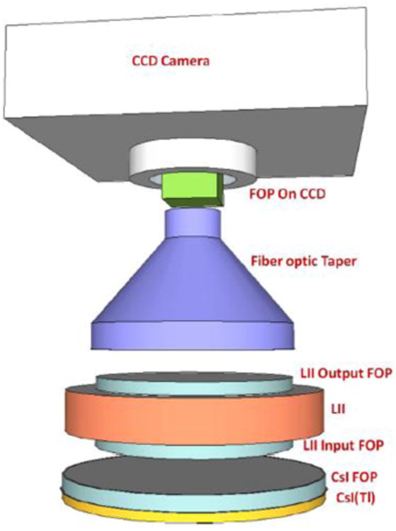
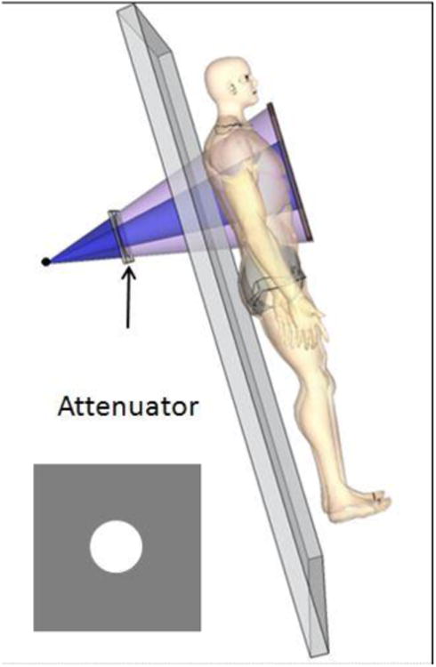
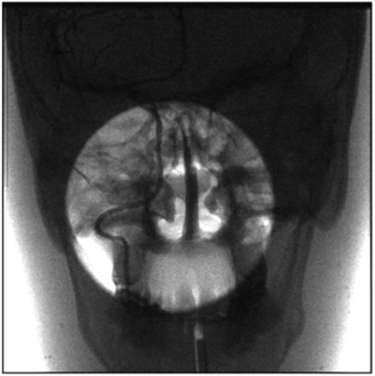
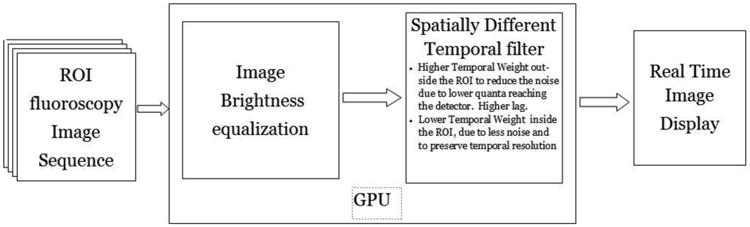
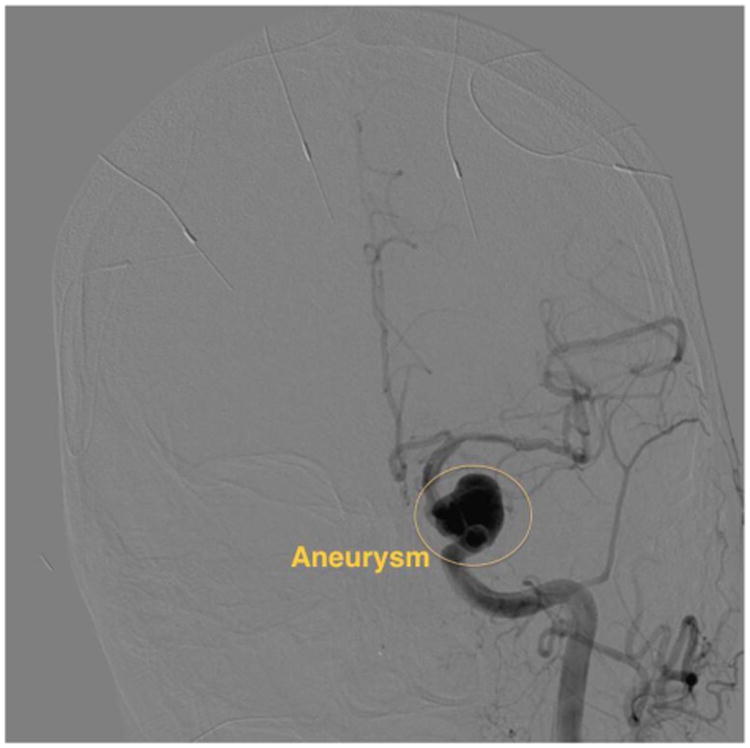
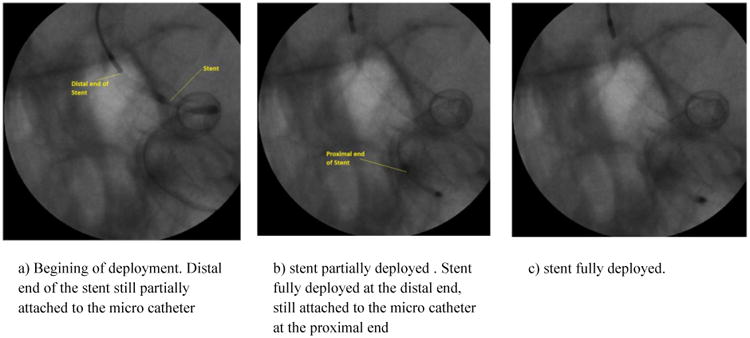
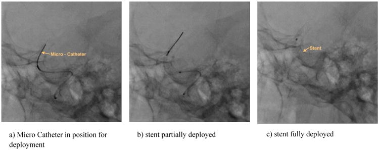
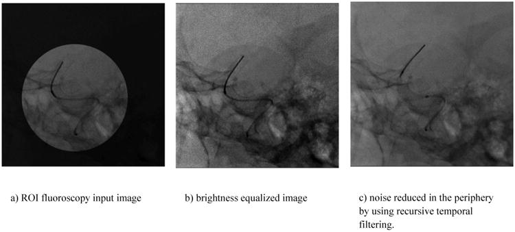
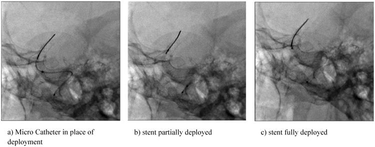
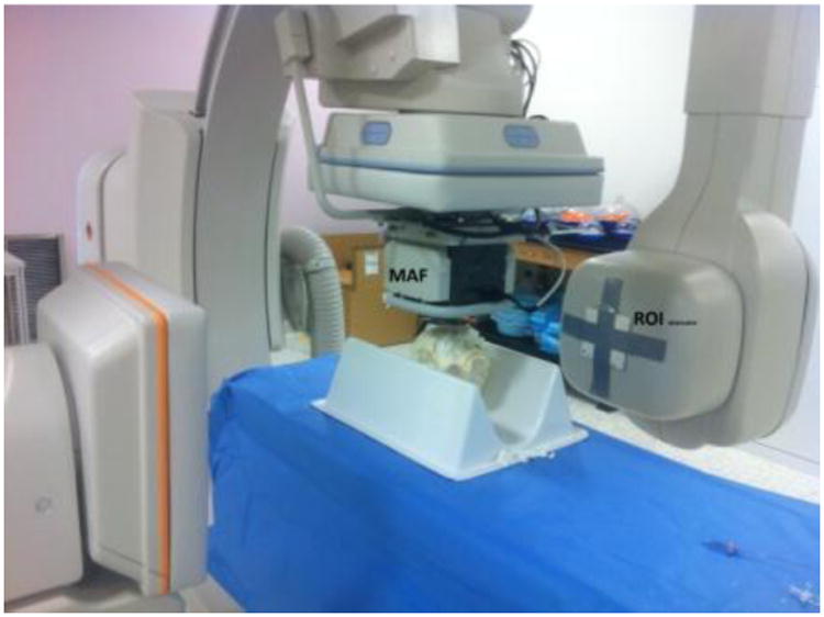
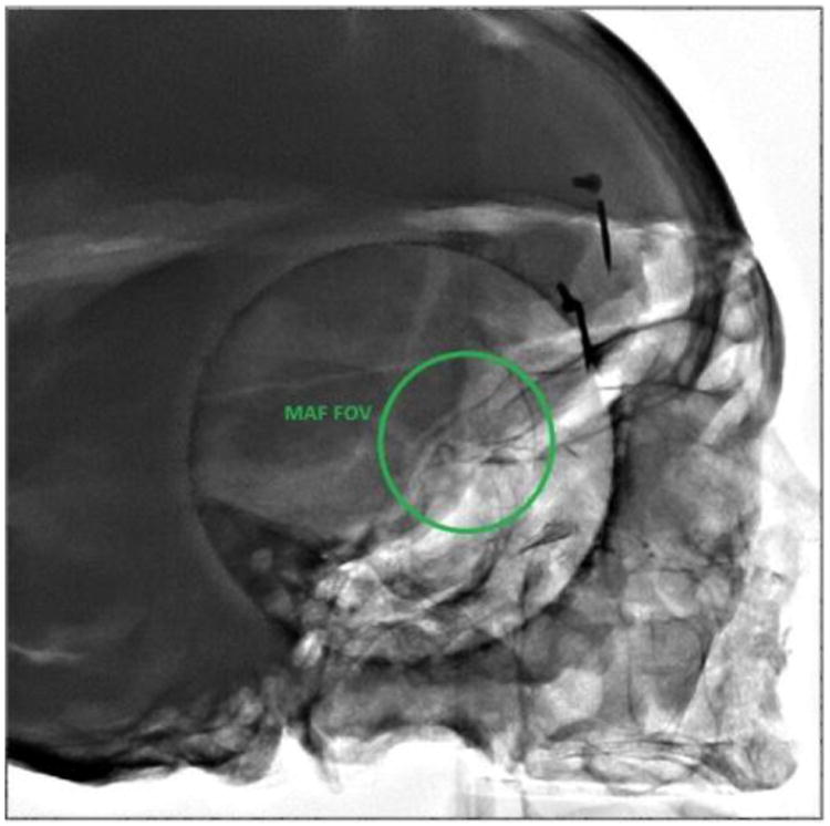
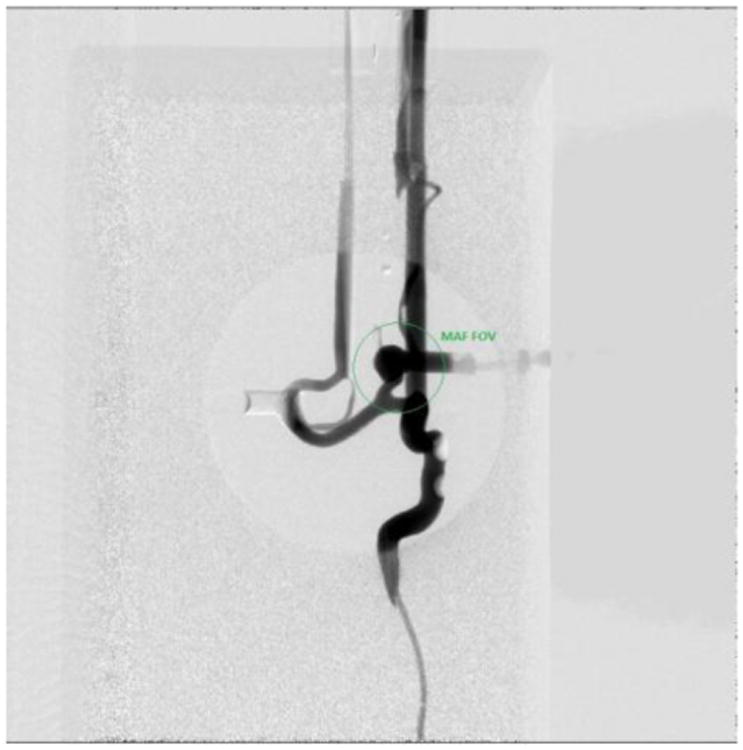
Endovascular-Image-Guided-Interventional (EIGI) treatment of neuro-vascular conditions such as aneurysms, stenosed arteries, and vessel thrombosis make use of treatment devices such as stents, coils, and balloons which have very small feature sizes, 10's of microns to a few 100's of microns, and hence demand a high resolution imaging system. The current state-of-the-art flat panel detector (FPD) has about a 200-um pixel size with the Nyquist of 2.5 lp/mm. For higher-resolution imaging a charge-coupled device (CCD) based Micro-Angio -Fluoroscope (MAF-CCD) with a pixel size of 35um (Nyquist of 11 lp/mm) was developed and previously reported. Although the detector addresses the high resolution needs, the Field-Of-View (FOV) is limited to 3.5 cm × 3.5 cm, which is much smaller than current FPDs. During the use of the MAF-CCD for delicate parts of the intervention, it may be desirable to have real-time monitoring outside the MAF FOV with a low dose, and lower, but acceptable, quality image. To address this need, a novel imaging technique for biplane imaging systems has been developed, using an MAF-CCD in the frontal plane and a dose-reduced standard large FOV imager in the lateral plane. The dose reduction is achieved by using a combination of ROI fluoroscopy and spatially different temporal filtering, a technique that has been previously presented. In order to evaluate this technique, a simulation using images acquired during an actual EIGI treatment on a patient, followed by an actual implementation on phantoms is presented.
Figures


References
-
- Rudin S, Bednarek DR, Hoffmann KR. Endovascular image guided interventions (EIGIs) Med Phys. 2008 Jan;35:301–309. http://www.ncbi.nlm.nih.gov/pubmed/18293585. - PMC - PubMed
-
- Jain A, Bednarek DR, Ionita C, Rudin S. A theoretical and experimental evaluation of the microangiographic fluoroscope: A high-resolution region-of-interest x-ray imager. Med Phys. 2011;38(7):4112–26. http://www.ncbi.nlm.nih.gov/pubmed/21859012. - PMC - PubMed
-
- Rudin S, Bednarek DR. Region of interest fluoroscopy. Med Phys. 1992;19(5):1183–1189. http://www.ncbi.nlm.nih.gov/pubmed/1435596. - PubMed
-
- Vasan SN, Sharma P, Ionita CN, Titus AH, Cartwright AN, Bednarek DR, Rudin S. Spatially different, real-time temporal filtering and dose reduction for dynamic image guidance during neurovascular interventions. Conf Proc IEEE Eng Med Biol Soc. 2011;2011:6192–6195. http://www.ncbi.nlm.nih.gov/pubmed/22255753. - PMC - PubMed
-
- Swetadri Vasan SN, Panse A, Jain A, Sharma P, Ionita Ciprian N, Titus AH, Cartwright AN, Bednarek DR, Rudin S. Dose reduction technique using a combination of a region of interest (ROI) material x-ray attenuator and spatially different temporal filtering for fluoroscopic interventions. Proc SPIE. 2012 Feb 23;8313:831357. doi: 10.1117/12.910945. Medical Imaging 2012: Physics of Medical Imaging. http://www.ncbi.nlm.nih.gov/pubmed/24027617. - DOI - PMC - PubMed
Grants and funding
LinkOut - more resources
Full Text Sources
Other Literature Sources