

Is there material loss at the backside taper in modular CoCr acetabular liners?
- PMID: 25318923
- PMCID: PMC4390963
- DOI: 10.1007/s11999-014-3982-2
Is there material loss at the backside taper in modular CoCr acetabular liners?
Abstract
Background: Metal wear and corrosion products generated by hip replacements have been linked to adverse local tissue reactions. Recent investigations of the stem/head taper junction have identified this modular interface as another possible source of metal debris; however, little is known regarding other modular metallic interfaces, their ability to produce metal debris, and possibly to provide insight in the mechanisms that produce metal debris.
Questions/purposes: We asked three questions: (1) can we develop a reliable method to estimate volumetric material loss from the backside taper of modular metal-on-metal liners, (2) do backside tapers of modular metal-on-metal liners show a quantifiable volumetric material loss, and, if so, (3) how do regions of quantitatively identified material loss correspond to visual and microscopic investigations of surface damage?
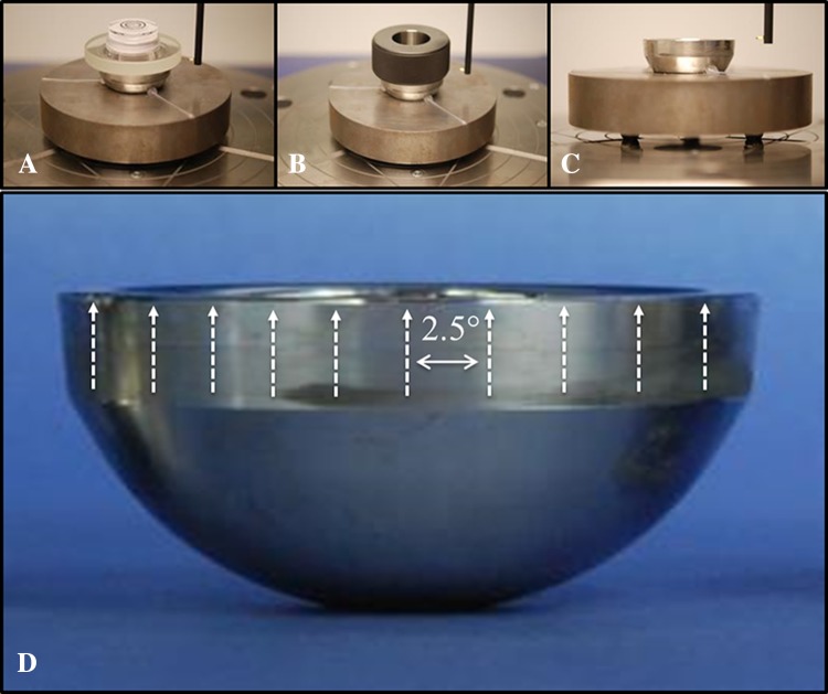
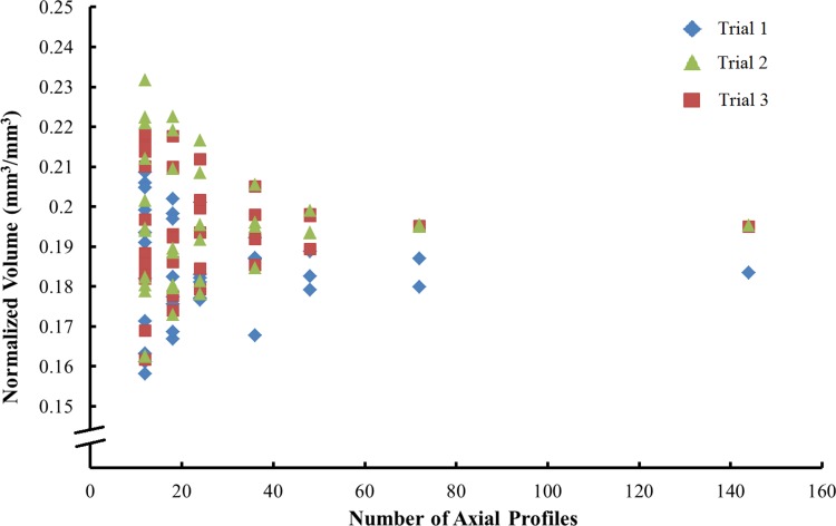
Methods: Twenty-one cobalt-chromium (CoCr) liners of one design and manufacturer were collected through an institutional review board-approved retrieval program. All liners were collected during revision surgeries, where the primary revision reason was loosening (n=11). A roundness machine measured 144 axial profiles equally spaced about the circumference of the taper region near the rim to estimate volume and depth of material loss. Sensitivity and repeatability analyses were performed. Additionally, visual and scanning electron microscopy investigations were done for three liners.
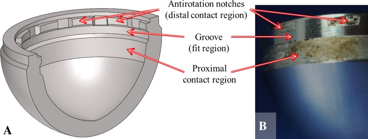
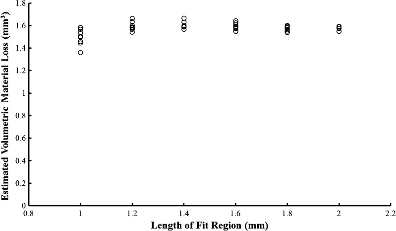
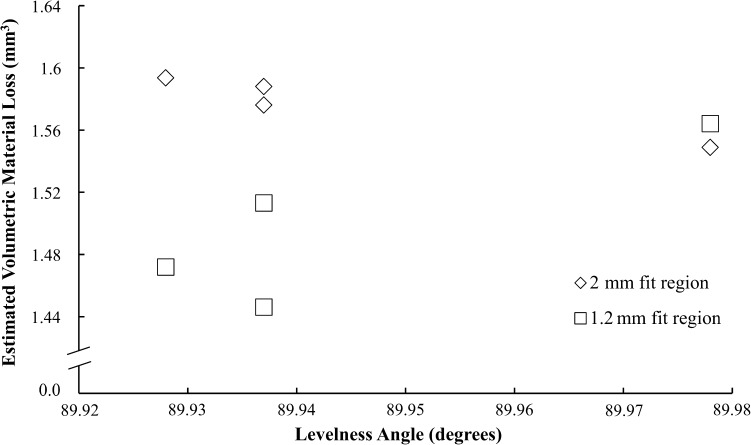
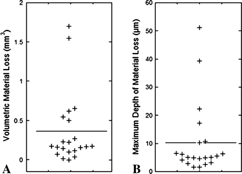
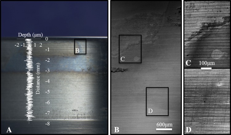
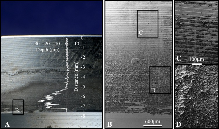
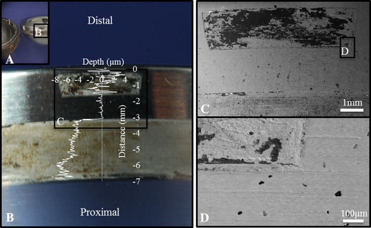
Results: Our measurement method was found to be reproducible. The sensitivity (how dependent measurement results are on experimental parameters) and repeatability (how consistent results are between measurements) analyses confirmed that component alignment had no apparent effect (weak correlation, R2=0.04) on estimated volumetric material loss calculations. Liners were shown to have a quantifiable material loss (maximum=1.7 mm3). Visual investigations of the liner surface could identify pristine surfaces as as-manufactured regions, but could misidentify discoloration as a possible region of material loss. Scanning electron microscopy more accurately distinguished between as-manufactured and damaged regions of the taper.
Conclusions: The roundness machine has been used to develop a repeatable method for characterizing material loss; future work comparing a gravimetric standard with estimations of material loss determined from the roundness machine may show the accuracy and effectiveness of this method. Liners show rates of material loss that compare with those reported for other taper junctions. Visual inspection alone may misidentify as-manufactured regions as regions of material loss.
Clinical relevance: This study identifies the acetabular liner/shell interface in modular metal-on-metal devices as a potential source of metal wear or corrosion products. The relation between metal debris and clinical performance, regardless of the type of bearing couple, is a concern for clinicians. Therefore, it is important to characterize every type of modular junction to understand the quantity, location, and mechanism(s) of material loss.
Figures
References
-
- Dunbar MJ. The proximal modular neck in THA: a bridge too far: affirms. Orthopedics. 2010;33:640. - PubMed
-
- Higgs GB, Hanzlik JA, MacDonald DW, Gilbert JL, Rimnac CM, Kurtz SM; Implant Research Center Writing Committee. Is increased modularity associated with increased fretting and corrosion damage in metal-on-metal total hip arthroplasty devices?: a retrieval study. J Arthroplasty. 2013;28(8 suppl):2–6. - PMC - PubMed
-
- Higgs GB, Hanzlik JA, MacDonald DW, Kane WM, Day JS, Klein GR, Parvizi J, Mont MA, Kraay MJ, Martell JM, Gilbert JL, Rimnac CM, Kurtz SM. Method of characterizing fretting and corrosion at the various taper connections of retrieved modular components from metal-on-metal total hip arthroplasty. In: Kurtz SM, Greenwald AS, Mihalko WM, Lemons J, editors. Selected Technical Papers 1560: Metal-on-Metal Total Hip Replacement Devices. West Conshohocken, PA: ASTM International; 2013. pp. 146–156.
Publication types
MeSH terms
Substances
Grants and funding
LinkOut - more resources
Full Text Sources
Medical
