

Three Dimensional Modeling of an MRI Actuated Steerable Catheter System
- PMID: 25328804
- PMCID: PMC4199243
- DOI: 10.1109/ICRA.2014.6907499
Three Dimensional Modeling of an MRI Actuated Steerable Catheter System
Abstract
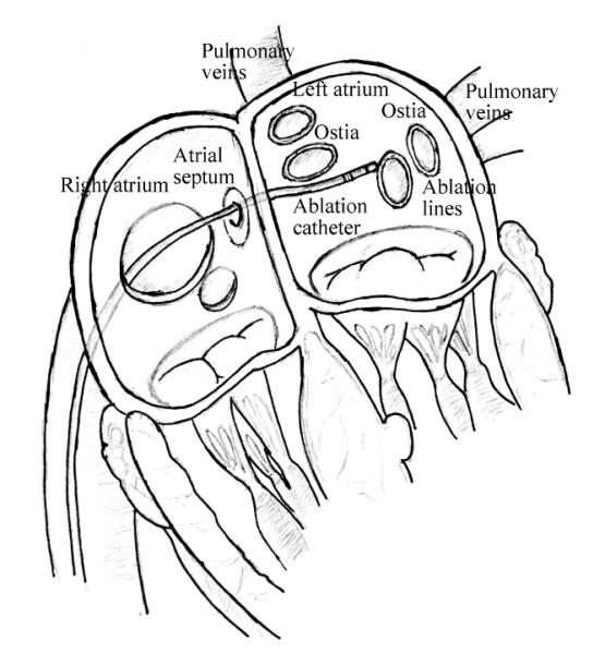
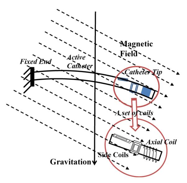
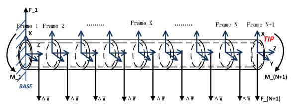
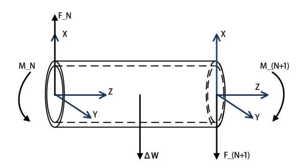
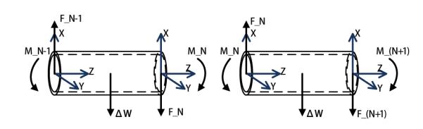
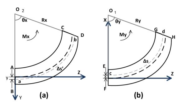
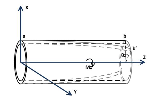
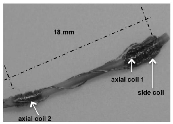
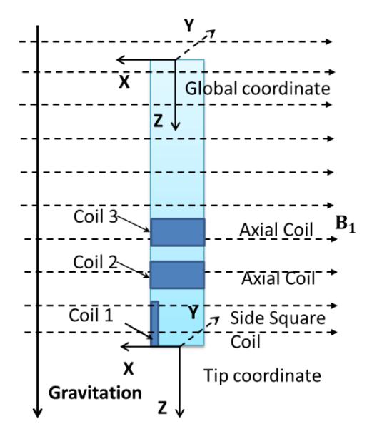
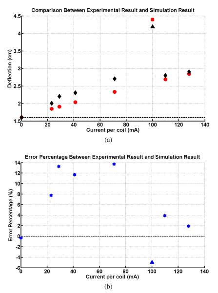
This paper presents the three dimensional kinematic modeling of a novel steerable robotic ablation catheter system. The catheter, embedded with a set of current-carrying micro-coils, is actuated by the magnetic forces generated by the magnetic field of the MRI scanner. This paper develops a 3D model of the MRI actuated steerable catheter system by using finite differences approach. For each finite segment, a quasi-static torque-deflection equilibrium equation is calculated using beam theory. By using the deflection displacements and torsion angles, the kinematic modeling of the catheter system is derived. The proposed models are evaluated by comparing the simulation results of the proposed model with the experimental results of a proof-of-concept prototype.
Figures
References
-
- What Is Catheter Ablation? National Heart Lung and Blood Institute; http://www.nhlbi.nih.gov/health/health-topics/topics/ablation/
-
- Niobe® ES Magnetic Navigation System. Stereotaxis; http://www.stereotaxis.com/niobe.html.
-
- Tunay I. Position control of catheters using magnetic fields. Mechatronics, 2004. ICM ’04. Proceedings of the IEEE International Conference; June 2004.pp. 392–397.
-
- — Modeling magnetic catheters in external fields. Proceedings of the 26th Annual International Conference of the IEEE EMBS; San Francisco, CA, USA. September 1-5, 2004.pp. 2006–2009. - PubMed
Grants and funding
LinkOut - more resources
Full Text Sources
Other Literature Sources